Other Parts Discussed in Thread: TLA2024,
Hello,
I am debugging a board which using MSP430F5438A to control TI ADC TLA2024 to sample external input signals, now the basic I2C communication is failed to establish, I asked this question on TLA2024 thread but no answer, is there somebody of MSP430F5438A experts can help me to address this problem?
Below are the SW codes, (because just few data need transfer, do not use interruption)
/* UCB2 initiation */
P9DIR |= 0x06; //P9.1 UCB2SDA, P9.2 UCB2SCL
P9OUT |=0x06;
for(i=0;i<20;i++) {}
P9OUT &=~0x06;
for(i=0;i<20;i++) {}
P9SEL |= 0x06; // Assign I2C pins to USCI_B2
UCB2CTL1 |= UCSWRST;
UCB2CTL0 = UCMST + UCMODE_3 + UCSYNC; //I2C Master, synchoronous mode
UCB2CTL1 = UCSSEL_2 + UCTR + UCSWRST; //SMCLK, enable SW reset
UCB2BR0 = 0x32; //SMCLK/50(0x32)=80kHz
UCB2BR1 = 0;
UCB2I2CSA = 0x48; //Slave ADC(TLA2024) Addr:100 1000(ADDR = 0)
UCB2CTL1 &= ~UCSWRST;
for(i=0;i<100;i++) {}
/* start to transmit data */
UCB2CTL1 |= UCTR; // uart in TX mode
while (IIC2_Start());
... ... omit other transmission codes
/* sub-function */
UINT8 IIC2_Start(void)
{
UCB2CTL1 |= UCTXSTT; // I2C start condition -- NOTE A
return(UCB2IFG & UCNACKIFG); -- NOTE B
}
Problem phenomenon description -
UCB2CTL1 is always cannot set bit UCTXSTT=1, that means cannot trigger a START condition correctly, then cannot continue following data transmission.
Problem phenomenon detail -
1. Before execute trigger start condition of NOTE A, UCB2 registers value are
UCB2CTL0 = 0x0F;
UCB2CTL1 = 0x90;
UCB2IFG = 0x00;
UCB2STAT = 0x00;
2. After execute the UCB3CTL1 |= UCTXSTT to trigger a start condition of NOTE A position, these registers value change to
UCB2CTL0 = 0x0F;
UCB2CTL1 = 0x90;
UCB2IFG = 0x022;
UCB2STAT = 0x50;
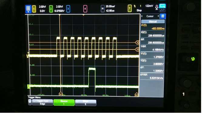
At this moment, the SCL and SDA signal wave as below picture,

Since this is the standard I2C communication sequence of MSP430F5438A, and the falling slope is pretty sharp, so just measured the rising slope of SCL and SDA signals,
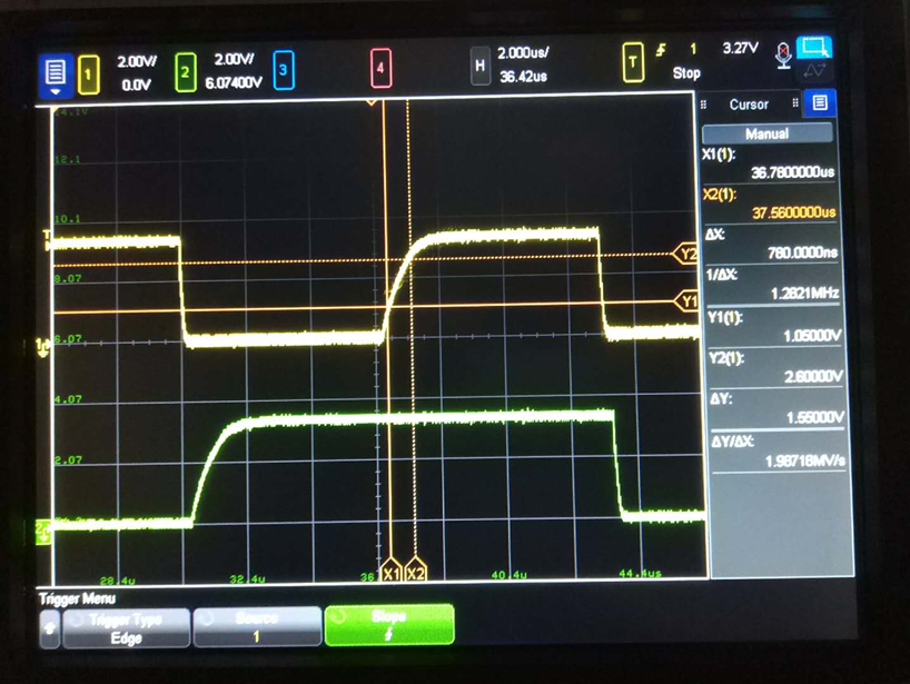

Both amplitude rising time from 30% to 70% are about 780ns, less than it’s maximum 1000ns as its datasheet description.
3.And then execute the next command return(UCB2IFG & UCNACKIFG) of NOTE B, then these registers value change to
UCB2CTL0 = 0x0F;
UCB2CTL1 = 0x90;
UCB2IFG = 0x22;
UCB2STAT = 0x50;
Because UCNACKIFG =1 of UCB3IFG, the command while (IIC2_Start()) became a dead loop.
To check whether there is any problem of UCB2 configuration or any UCB2 hardware problem, I changed this I2C connection to UCB3, the UCB3 is also work well with another I2C component, the codes is almost the same, except slave address, then change the address to 0x48 as TLA2024 hardware, the results are,
1. Before execute trigger start condition of NOTE A, UCB2 registers value are
UCB3CTL0 = 0x0F;
UCB3CTL1 = 0x90;
UCB3IFG = 0x00;
UCB3STAT = 0x00;
2. After execute the UCB3CTL1 |= UCTXSTT to trigger a start condition of NOTE A position, these registers value change to
UCB3CTL0 = 0x0F;
UCB3CTL1 = 0x92;
UCB3IFG = 0x02;
UCB3STAT = 0x50;
The SCL and SDA wave of this moment as below,
3. And then execute the next command return(UCB2IFG & UCNACKIFG) of NOTE B, then these registers value change to
UCB3CTL0 = 0x0F;
UCB3CTL1 = 0x90;
UCB3IFG = 0x22;
UCB3STAT = 0x50;
Because UCNACKIFG =1 of UCB3IFG, the comand while (IIC2_Start()) became a dead loop.
The hardware schematic as below,

Appreciate your support in advance!
Best Regards!
QM