Other Parts Discussed in Thread: MSP-EXP430FR5739
Hi,
I am trying to do timer capture on TB1. This timer is running off of SMCLK (24 MHz DCOCLK) and should be synchronous with the CPU. I am using an asynchronous external signal to do the capture on CCR0 from CCI0A on P2.2. The external signal can be very fast, on the order of 50 kHz and up.
I have been researching the SCS synchronization mode and when/how it should be used. (Refer to this and this.) In my case, since the timer is using the same clock source as the CPU, I can read TB1R directly in software without needing to do any tricks (e.g. software-triggered capture or consecutive reads of TB1R). For my CCR0 external capture, it seems that I should be using SCS to avoid asynchronous captures while TB1R is (potentially) transitioning. So my timer is configured as follows:
TB1CTL = TBSSEL_2 | MC_2;               // use SMCLK, continuous mode
TB1CCTL0 = CM_3 | CCIS_0 | SCS | CAP;   // both edges, CCI0A, synchronize, capture mode
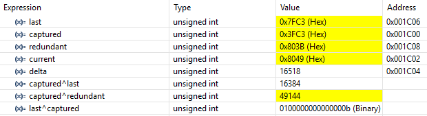
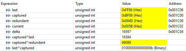
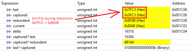
Indeed I have had no trouble reading TB1R anytime. But if I read TB1CCR0 in a tight loop with no regard for CCIFG, I will sometimes get data corruption. The following code will fail after around 10,000 - 200,000 iterations:
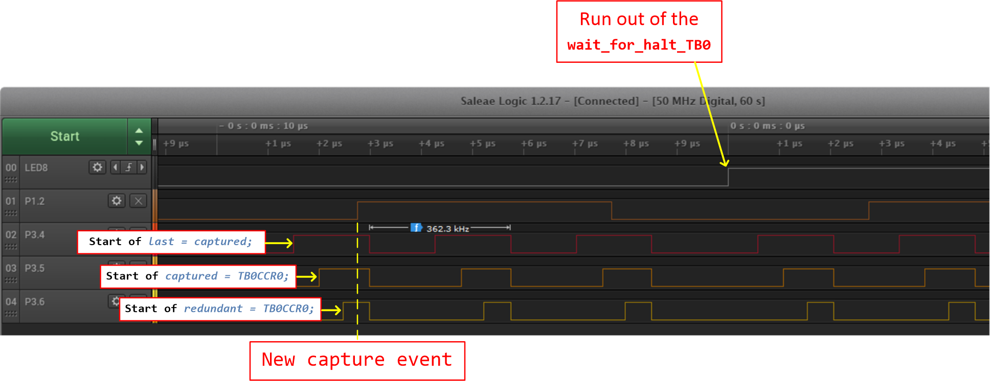
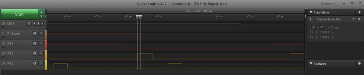
void wait_for_halt(void) {
    uint16_t timer_current, timer_captured, timer_delta;
    do {
        timer_captured = TB1CCR0;
        timer_current = TB1R;
        timer_delta = timer_current - timer_captured;
    } while(timer_delta < 300);
}
But this always works by testing CCIFG:
void wait_for_halt(void) {
    uint16_t timer_current, timer_captured, timer_delta, timer_flag;
    do {
        TB1CCTL0 &= ~(CCIFG | COV);
        timer_captured = TB1CCR0;       // this read does NOT clear CCIFG
        timer_flag = TB1CCTL0 & CCIFG;  // timer_captured is invalid if CCIFG appeared during read
        timer_current = TB1R;
        timer_delta = timer_current - timer_captured;
    } while(timer_flag != 0 || timer_delta < 300);
}
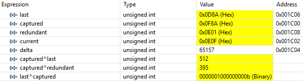
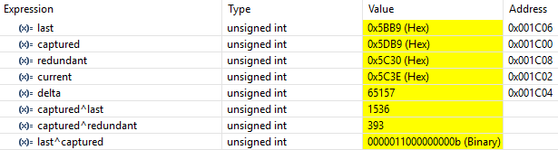
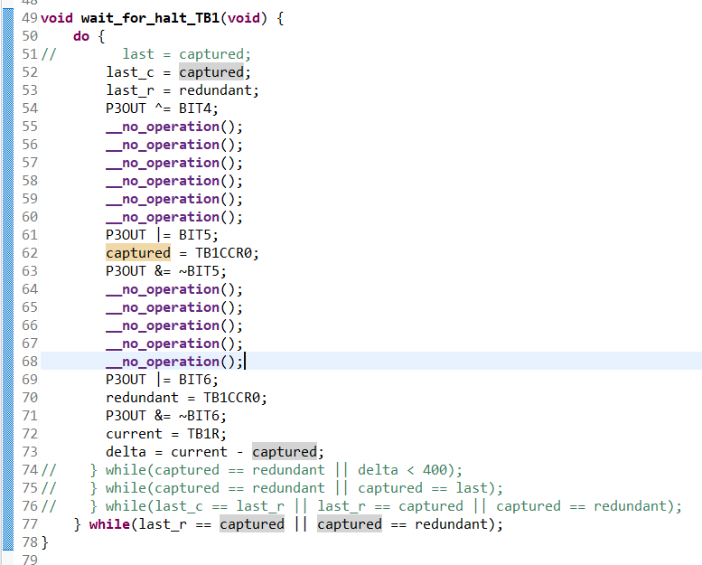
And this works by reading the register twice:
void wait_for_halt(void) {
    uint16_t timer_current, timer_captured, timer_redundant, timer_delta;
    do {
        timer_captured = TB1CCR0;
        timer_redundant = TB1CCR0;
        timer_current = TB1R;
        timer_delta = timer_current - timer_captured;
    } while(timer_captured != timer_redundant || timer_delta < 300);
}
My question is: Why do I need to do this? I presume that none of these registers are buffered. That would explain why you need to bend over backwards to read TB1R if using an external clock to drive the timer. But why would I have this issue with TB1CCR0, especially given that the SCS synchronization mode is enabled? I would think that this would cause the register to update synchronously with the timer and CPU; meaning I could just read it anytime. Or is the synchronization causing the register to sometimes update at the exact moment that my read is taking place?
I have experimented with SCS disabled. As expected, this fails regularly and none of the implementations above help.
On a side note, I understand that this example could be implemented by simply watching for transitions on the input and tracking the time in software. But I need to be able to detect a lack of signal immediately upon entry to the function.