This thread has been locked.

If you have a related question, please click the "Ask a related question" button in the top right corner. The newly created question will be automatically linked to this question.

MSP430FR5969: BSL Configuration using CP2102.

Part Number: MSP430FR5969
Other Parts Discussed in Thread: MSP-FET

Hi all,

I am designing a custom PCB employing a MSP430FR5969, being programmed using CP2102 in a similar fashion after referring to this blog;

and

and

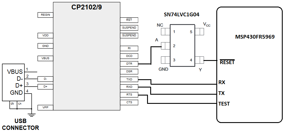
after going through above links I have developed the following schematic ;

Q1. Is the schematic correct?

Q2. Is connection of DTR (of CP2102) needs to inverted and then connected to RESET of MSP430FR5969?

Q3. Do I need to take care of any other precaution?

Thanks and regards


  • The second reference in your post concerns using a CP2102 to program a G2553 device.  The G2553 is an older device which is programmed with TI's software BSLDEMO.exe.  That program  directly outputs the required pulses on DTR and RTS to initiate BSL, although the polarity of DTR is wrong when using the CP2102.

    However, the FR5969 is a newer part with completely different BSL protocols than the G2553.  It is programmed with TI's BSL Scripter software.  Unfortunately, Scripter does not generate the DTR and RTS pulses at all.  It depends on a "Rocket" or MSPFET programming device to do that. 

    So I do not believe your idea will work unless (1) you write your own software to program the FR5969, (2) you re-write BSL Scripter to give it the option of issuing the DTR and RTS pulses directly, or (3) TI does that re-write for you (and for all of us).

    In the past I tried to understand what is addressed in your first reference, but was unable to make sense of it.  All of the internal links are broken, and I just couldn't understand what he was doing.

    So far as I know, no one has been successful at using a simple CP2102 adapter, or one like it, without a Rocket, MSPFET or equivalent third-party device, with BSL Scripter.  This is unfortunate because if a product requiring BSL Scripter is sent out to customers, there is no practical way to do firmware updates except to include a programming device that may cost more than the product itself.  This is not the case with the older parts using BSLDEMO since the CP2102 modules are very inexpensive, and a CP2102 can even be embedded in the project circuit for a couple dollars.

  • Hi Swaroop,

    As George's reply, do you have any feedback?
  • Hi Wei.Jetim Zhao,
    I am sorry but George's reply did not solve my issue. My MSP430FR5696 Launchpad has just arrived. I'll try with it and give feedback accordingly.

    thanks and regards!!
    Swaroop
  • Hi swarrop,

    That's okay. Please feedback after your testing. I will be glad to help your issue.
  • Hi Swaroop,

    Any testing result?

  • My first response dealt with the software to be used to flash the FR5969.  I should have also addressed your hardware questions.

    Q1.  The schematic looks correct assuming you need to invert the CP2102 DTR output.  But also see Q3 about the state of these connections when the CP2102 is powered down.  Also, you don't show how the CP2102 will be powered.  The data sheets for the CP2102/9, and for the CP2102N (v1.2 of the datasheet) recommended for new designs, have excellent diagrams for the various powering options.  In any case, I believe you will need to connect the VBUS input back to the USB 5V line, probably through a divider, to enable the CP2102.  My understanding is that the CP2102(N) will not operate at all unless it senses that USB is connected.

    Q2.  The issue of inverting DTR is entirely a function of what software you use to generate the DTR/RTS signalling pattern.  If you can connect a scope to those outputs, the pattern generated when the software starts should look like Figure 2 of Section 3.3.2 of SLAU550P. 

    Q3.  Be aware that when the CP2102 is powered down, all of it's I/O  pins become sinks - they behave as though they are connected to ground through a resistor.  This can complicate things if the CP2102 is powered from the USB bus, but the FR5969 is powered from another source.  The biggest problem usually involves the DTR output if inversion isn't needed.  DTR is normally high when idle, but when the CP2102 is powered down, DTR will go low.  If it is directly connected to /Reset of the FR5969, that may hold the processor in perpetual reset, which is not what you want.  While not directly relevant to the FR5969, I posted a long-winded PDF on Github about interfacing a CP2102 to MSP430G parts, and there's discussion about the hardware beginning on page 11 that may be helpful.

    gbhug5a-MSP430-BSL MSP430G BSL Using an Embedded USB-to-Serial Adapter

    I am still curious about what software you will be using for this BSL.  I hope you will post the detals about that.

  • thanks a ton George for your valuable inputs.

    I am working with another member of our team on this and we are bit occupied with some other stuff.

    Our MSP430FR5969 launchpad has just arrived. I will try to post some results by next week.

    I'll go through the link you mentioned, if I face any problems l'll post it here.

    Thanks and regards

    Swaroop

  • George Hug said:

    The second reference in your post concerns using a CP2102 to program a G2553 device.  The G2553 is an older device which is programmed with TI's software BSLDEMO.exe.  That program  directly outputs the required pulses on DTR and RTS to initiate BSL, although the polarity of DTR is wrong when using the CP2102.

    However, the FR5969 is a newer part with completely different BSL protocols than the G2553.  It is programmed with TI's BSL Scripter software.  Unfortunately, Scripter does not generate the DTR and RTS pulses at all.  It depends on a "Rocket" or MSPFET programming device to do that. 

    So I do not believe your idea will work unless (1) you write your own software to program the FR5969, (2) you re-write BSL Scripter to give it the option of issuing the DTR and RTS pulses directly, or (3) TI does that re-write for you (and for all of us).

    In the past I tried to understand what is addressed in your first reference, but was unable to make sense of it.  All of the internal links are broken, and I just couldn't understand what he was doing.

    So far as I know, no one has been successful at using a simple CP2102 adapter, or one like it, without a Rocket, MSPFET or equivalent third-party device, with BSL Scripter.  This is unfortunate because if a product requiring BSL Scripter is sent out to customers, there is no practical way to do firmware updates except to include a programming device that may cost more than the product itself.  This is not the case with the older parts using BSLDEMO since the CP2102 modules are very inexpensive, and a CP2102 can even be embedded in the project circuit for a couple dollars.

    I was able to generate the BSL invoke sequence mentioned in SLAU550(Figure 2, Page No.- 7) with the following code:

    Link

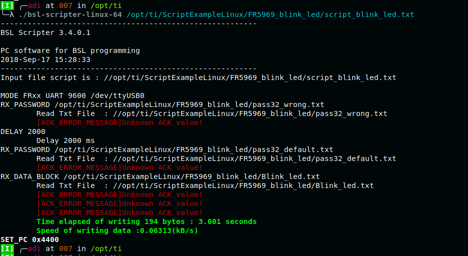
    But when I tried to run the BSL_scripter after running this, I got the following output:


    I'm using cp2102 with MSP430FR5969 and compiled the BSL_invoke.c with GCC 8.2.1 20180831 under Manjaro Linux.

    #include <stdio.h>
    #include <fcntl.h>   	 /* File Control Definitions           */
    #include <termios.h>	 /* POSIX Terminal Control Definitions */
    #include <unistd.h> 	 /* UNIX Standard Definitions 	       */ 
    #include <errno.h>   	 /* ERROR Number Definitions           */
    #include <sys/ioctl.h>   /* ioctl()                            */     
    #include <stdlib.h>
    #include <time.h>
    #include <unistd.h>
    
    
    struct timespec ts;
    
    
    void sleep_ms(int milliseconds)
    {
        ts.tv_sec = milliseconds / 1000;
        ts.tv_nsec = (milliseconds % 1000) * 1000000;
        nanosleep(&ts, NULL);
    }
    
    
    void main(void)
    {
    	int fd;	/*File Descriptor*/
    
    
    	/*------------------ Opening the Serial port ------------------*/
    	/* Change /dev/ttyUSB0 to the one corresponding to your system */
    	/* O_RDWR Read/Write access to serial port           */	
    	/* O_NOCTTY - No terminal will control the process   */
    	/* Blocking Mode  */
    	fd = open("/dev/ttyUSB0",O_RDWR | O_NOCTTY );	 
    
    			   						                       
    	/* Error Checking */									
    	if(fd == -1) {						
        		printf("\n    Error! in Opening ttyUSB0  ");
        	}
        	else {
        		//printf("\n    ttyUSB0 Opened Successfully \n");
    	}
    		
    
    	/*--------- Controlling the RTS and DTR pins of CP2102 to generate BSL invoke sequence --------*/
    	int RTS_flag, DTR_flag;
    
    	RTS_flag = TIOCM_RTS; /* Modem Constant for RTS pin */
    	DTR_flag = TIOCM_DTR; /* Modem Constant for DTR pin */
    	
    	/* Initially making RTS and DTR line HIGH as whenever the /dev/ttyUSB0 port is 
    	opened, DTR and RTS becomes LOW by default */	
    	ioctl(fd, TIOCMBIC, &RTS_flag); /* TIOCMBIC - Clear the bit corrosponding to  RTS_flag */
    	ioctl(fd, TIOCMBIC, &DTR_flag); /* TIOCMBIS - Set the bit corrosponding to  DTR_flag */
    	sleep_ms(3000);
    
    	/* Genrating the BSL invoke sequence as mentioned in SLAU550(Figure 2, Page No.- 7) */
    	ioctl(fd,TIOCMBIS,&RTS_flag);
    	sleep_ms(10);
    	ioctl(fd,TIOCMBIC,&RTS_flag); 
    										
    	sleep_ms(100);
    
    	ioctl(fd,TIOCMBIS,&RTS_flag);
    	sleep_ms(10);
    	ioctl(fd,TIOCMBIS,&DTR_flag); 
    	sleep_ms(10);
    	ioctl(fd,TIOCMBIC,&RTS_flag);
    	
    	sleep_ms(2000);
    		
    	/* Close the Opened Serial Port */
    	close(fd);
    }
    

    Also attached the example script that I used with BSL_scripter

    MODE FRxx UART 9600 /dev/ttyUSB0
    RX_PASSWORD /opt/ti/ScriptExampleLinux/FR5969_blink_led/pass32_wrong.txt
    DELAY 2000 
    RX_PASSWORD /opt/ti/ScriptExampleLinux/FR5969_blink_led/pass32_default.txt
    RX_DATA_BLOCK /opt/ti/ScriptExampleLinux/FR5969_blink_led/Blink_led.txt
    SET_PC 0x4400

    @4400
    81 00 00 24 B1 13 00 00 B1 13 5A 00 0C 43 B1 13 
    2C 00 1C 43 B1 13 54 00 32 D0 10 00 FD 3F 03 43 
    @ff80
    FF FF FF FF FF FF FF FF FF FF FF FF FF FF FF FF 
    @ffcc
    18 44 18 44 18 44 18 44 18 44 18 44 18 44 18 44 
    18 44 18 44 18 44 18 44 18 44 18 44 18 44 18 44 
    18 44 18 44 18 44 18 44 18 44 18 44 18 44 18 44 
    18 44 00 44 B2 40 00 A5 A0 05 3F 40 40 04 82 4F 
    A6 05 3F 40 40 04 82 4F A4 05 3F 40 13 15 82 4F 
    A8 05 3F 40 01 A5 82 4F A0 05 C2 43 A1 05 10 01 
    F1 03 B2 40 80 5A 5C 01 92 C3 30 01 D2 D3 04 02 
    D2 E3 02 02 B1 40 10 27 00 00 91 83 00 00 81 93 
    00 00 F6 27 FA 3F 03 43 03 43 FF 3F 03 43 1C 43 
    10 01 
    q
    

    @FFE0
    FF FF FF FF FF FF FF FF FF FF FF FF FF FF FF FF
    FF FF FF FF FF FF FF FF FF FF FF FF FF FF FF FF
    q   

    @FFE0
    FF FF FF FF FF FF FF FF FF FF FF FF FF FF FF FF
    FF FF FF FF FF FF FF FF FF FF FF FF FF FF 00 00
    q   

  • First, I should say that I know nothing about Linux.  So I have to leave it to you to make sure that the designation of the COM port in the MODE line is correct.  In Windows it would be the name of the virtual COM port created by the Silabs driver, and there would be no mention of "USB".  But I don't know how that works in Linux.

    Otherwise, I'd suggest you try adding PARITY at the end of the MODE line. SLAU655F says Scripter defaults to no parity, but almost all BSLs require even parity.  Normally the Rocket or MSP-FET generates the parity bit, but since you are using the CP2102, I think you need to turn on even parity in Scripter, which is done by adding PARITY to the MODE line.

    For testing, after sending the wrong password leading to mass erase, followed by the default password, I suggest you just do a TX_BSL_VERSION just to see if everything is working in both directions.

    Thanks very much for the DTR/RTS code.  If you have a link to a Windows version, that would be helpful.  Otherwise I may try to write one.  I think having a separate executable generate the BSL entry pattern in advance of running Scripter will be very useful, and will permit using standard USB-to-UART adapters like the CP2102 with Scripter.

    Please let me know if PARITY works.

    Edit:  I thought of another possible problem.  If Scripter intializes DTR and RTS when it opens the COM port, then this method may not work.  If Scripter takes DTR low at the beginning, then the FR5969 will reset, and the BSL session will be cancelled.  Taking RTS to the wrong state may not be a big problem if it is only temporary.  Your code must leave these lines at the correct state after initiating the BSL session (DTR high, RTS low), and Scripter must not change them when it runs.

  • George Hug said:

    Edit:  I thought of another possible problem.  If Scripter intializes DTR and RTS when it opens the COM port, then this method may not work.  If Scripter takes DTR low at the beginning, then the FR5969 will reset, and the BSL session will be cancelled.  Taking RTS to the wrong state may not be a big problem if it is only temporary.  Your code must leave these lines at the correct state after initiating the BSL session (DTR high, RTS low), and Scripter must not change them when it runs.

    I wrote a Windows version of your program, and when it exits it leaves the two lines in the correct state - /Reset is high and TEST is low.  But when BSL-Scripter runs, it resets the DTR line, and with /Reset low the processor cannot function.  I got the same error you did, but with no device attached, so I think it's likely that your FR5969 is in reset when Scripter is running, and is doing nothing.

    I don't know what the solution to this is except to recompile Scripter so that it leaves DTR and RTS as it finds them.  But that may mess things up for using the Rocket or MSP-FET.

    I did my testing using a script.  I did not check Scripter's command line mode to see if it also brings DTR low, but will try that if I get time.  I would be surprised if that makes any difference..

    So I would say that this isn't looking promising.  The best solution is still getting TI to modify Scripter with an option that lets it work with generic adapters like the CP2102.

  • Hi George,

    George Hug said:
    First, I should say that I know nothing about Linux.  So I have to leave it to you to make sure that the designation of the COM port in the MODE line is correct.  In Windows it would be the name of the virtual COM port created by the Silabs driver, and there would be no mention of "USB".  But I don't know how that works in Linux.

    I checked for the port name, it is correct and its opening the port successfully.

    George Hug said:

    Otherwise, I'd suggest you try adding PARITY at the end of the MODE line. SLAU655F says Scripter defaults to no parity, but almost all BSLs require even parity.  Normally the Rocket or MSP-FET generates the parity bit, but since you are using the CP2102, I think you need to turn on even parity in Scripter, which is done by adding PARITY to the MODE line.

    For testing, after sending the wrong password leading to mass erase, followed by the default password, I suggest you just do a TX_BSL_VERSION just to see if everything is working in both directions.

    Ok, will try this.

    George Hug said:
    Thanks very much for the DTR/RTS code.  If you have a link to a Windows version, that would be helpful.  Otherwise I may try to write one.  I think having a separate executable generate the BSL entry pattern in advance of running Scripter will be very useful, and will permit using standard USB-to-UART adapters like the CP2102 with Scripter.

    Seems like you already figured out but anyway, this link migh be helpful.

    George Hug said:
    Edit:  I thought of another possible problem.  If Scripter intializes DTR and RTS when it opens the COM port, then this method may not work.  If Scripter takes DTR low at the beginning, then the FR5969 will reset, and the BSL session will be cancelled.  Taking RTS to the wrong state may not be a big problem if it is only temporary.  Your code must leave these lines at the correct state after initiating the BSL session (DTR high, RTS low), and Scripter must not change them when it runs.

    I checked the signals through logic analyzer. when BSL scripter starts, it pulls down the DTR and RTS lines of CP2102. I have gone through its code, I think it is using libusb for controlling the RTS and DTR lines. We may have to recompile the BSL scripter code to remove that DTR/RTS part.

    When BSL-scripter is transmitting then MSP430FR5969 is giving some reply as shown in the below image(look for TXD and RXD line):

  • George Hug said:
    I wrote a Windows version of your program, and when it exits it leaves the two lines in the correct state - /Reset is high and TEST is low.  But when BSL-Scripter runs, it resets the DTR line, and with /Reset low the processor cannot function.  I got the same error you did, but with no device attached, so I think it's likely that your FR5969 is in reset when Scripter is running, and is doing nothing.

    I have changed the invoke sequence part in the code as the previous one was generating incorrect sequence(Updated the repository). I also found out that tSBW,EN must be between 250ns(slau550p, Page 7, Figure 2) and 110us(MSP430FR5969 datasheet, Page 52, Table 5-35)(Added sleep_us function in the repository to deal with this). But with my code, I wasn’t able to generate tSBW,EN less than 386us(As our systems are multi-threaded so maybe the OS is handling some other process instead of the sleep_us function). Would look for some way to generate accurate timestamps. I haven’t gone through the BSLdemo code, but as you are quite familiar with it and you also mentioned before that it does generate those DTR/RTS sequence, so which system library do they use for that?

    Following is the generated invoke sequence:


    Looks right to me(According to slau550p, Page 7, Figure 2). I also made the TEST line LOW well before starting the invoke sequence(mentioned in slau550p)(This wasn’t there in the previous version of my code). Let me know if there is something wrong with it.

    George Hug said:
    I don't know what the solution to this is except to recompile Scripter so that it leaves DTR and RTS as it finds them.  But that may mess things up for using the Rocket or MSP-FET.

    Yes, most probably we have to recompile it. We can add an option to choose between Rocket, MSP-FET or CP2102(can be given in the argument)

  • I couldn't get the quote function to work, so I'm doing it this way:

     > I have changed the invoke sequence part in the code as the
     > previous one was generating incorrect sequence(Updated the
     > repository). I also found out that tSBW,EN must be between
     > 250ns(slau550p, Page 7, Figure 2) and 110us(MSP430FR5969
     > datasheet, Page 52, Table 5-35)(Added sleep_us function in
     > the repository to deal with this). But with my code, I
     > wasn’t able to generate tSBW,EN less than 386us(As our
     > systems are multi-threaded so maybe the OS is handling some
     > other process instead of the sleep_us function). Would look
     > for some way to generate accurate timestamps. I haven’t
     > gone through the BSLdemo code, but as you are quite
     > familiar with it and you also mentioned before that it does
     > generate those DTR/RTS sequence, so which system library do
     > they use for that?

    I don't believe that is the correct interpretation of tSBW.EN.  Please note in the text above Figure 2:

    "The first high level of the TEST pin must be at least tSBW, En (see device-specific data sheet for tSBW, En parameter)".

    So in effect it is the minimum duration of the first positive TEST pulse.  By comparison, the G2553 has a tSBW,EN maximum of 1 uS, but the actual pulse produced by BSLDEMO is 15 mS.  And that works quite well.  Perhaps someone with a Rocket or MSP-FET can measure the actual duration it produces for FRxx parts.

    BSLDEMO is a generation earlier than Scripter.  It is written in C, and doesn't use any third party environment, just standard Windows calls to toggle the DTR and RTS levels.  I don't believe there is a Linux or Mac version.

    I don't understand the Scripter source code.  The only occurrence of "DTR" anywhere in the source code is in TestReset.h, but I don't understand what it's doing, or how it gets executed.  If you re-write the code, I think the way to do it might be to provide for an additional MODE line option, perhaps called ADAPTER, which if present would bypass whatever code is changing the lines, and substitute code which does the DTR/RTS pattern.

  • I've posted in a separate thread asking for clarification on tSWB,En.

    There's one other possibility that might work for you in Linux, but possibly not in Windows.  I'm told by a friend that there may be a way to block entry to the particular Linux routine that Scripter calls to change DTR and RTS.  That might be inserting a hook so that the call simply returns with no error, but doesn't do anything.  Or there may be a formal way of doing that within Linux.  Anyway, the idea would be to run your program that transmits the BSL invoke sequence, and which also blocks further changes to those lines, then run Scripter, then finally run another program that reverses the blocking and returns things to normal.  Or it might possibly involve running Scripter from within your invocation program.

    The advantage of doing something like this is not having to modify Scripter at all.  It is updated regularly as support for new parts is added, and it would be best not to have to modify each Scripter update.

  • Hi George,

    So I would say that this isn't looking promising. The best solution is still getting TI to modify Scripter with an option that lets it work with generic adapters like the CP2102.
    [Wei] Sure, I will feedback to our tools team for the future development plan.
  • Wei.Jetim Zhao said:
    Hi George,

    So I would say that this isn't looking promising. The best solution is still getting TI to modify Scripter with an option that lets it work with generic adapters like the CP2102.
    [Wei] Sure, I will feedback to our tools team for the future development plan.

    Thanks for the offer.  If the family is one that requires the invoke pattern on /Reset and Test, and if the mode is UART, then perhaps there could be an "ADAPTER" or "INVOKE" option on the MODE line that would cause Scripter to perform the invoke pattern itself.  I don't believe there would be any other changes needed.  After all, we have  the SLAA535a.pdf G2 launchpad and G2231 setup, which does nothing but do the invoke pattern and add even parity, and Scripter seems to work fine with that setup.

    However, a while back I took a run at getting a similar change for BSLDEMO, but due to miscommunication the change made wasn't what was needed, and that change has since been removed.  So I'm not sure how much interest your tools team will have in  this.  My feeling is that TI would certainly sell fewer Rockets, but it might sell many more MSP430s.  Designers could embed a very low cost adapter in a project, which would allow customers to update firmware with only a USB cable and Scripter.

  • Aaditya,

    There is a way to solve this that isn't very elegant, but would not require recompiling Scripter.  You could set things up so the lines connecting DTR and RTS from the CP2102 to /Reset and Test  on the FR5969 could be easily and quickly disconnected or switched off - either mechanically or electronically.  You would first run your program that generates the invoke pattern on DTR and RTS, then disconnect DTR and RTS from the FR5969, then run Scripter.  The /Reset pin should already have an external pullup resistor, and Test has an internal pulldown resistor.  Your program would leave /Reset (DTR) high and Test (RTS) low, which is the normal state for the FR5969, and the pullup/pulldown resistors will maintain that state when the lines are disconnected.  Then it won't matter if Scripter does strange things with DTR and RTS.

    If that's not a practical solution for your project, it might at least be good to confirm that flashing does work with this method using Scripter and a CP2102.

    Edit:  It's possible only DTR would need to be disconnected.  I haven't fully tested it, but if Scripter brings RTS low, and keeps it there, thatmay be ok. If that's the case, it's only DTR going low that messes things up.

    Another solution would be specific to the CP2102N part - the new version.  In addition to the usual UART pins, even the 20-pin package also has four GPIO pins that unfortunately are configured as inputs by default, but can be reconfigured as outputs, and you could use two of them to generate the /Reset and Test pattern, and not even connect DTR and RTS.  But that would require you to configure the chips in advance, and your program to generate the invoke pattern would require the Silabs runtime DLL to be present.  This is a lot of extra trouble, but it seems it should work if you are embedding the CP2102N on your board.

    Of course none of this would be necessary if TI adds the appropriate option to Scripter, as discussed earlier.

  • Hi George,

    I would thanks for your involving of this thread and give so many useful information and solutions.
    I'm still catching up with the discussion but I would like to click some of your replies as "TI Thinks Revolved" because they will be useful about the similar topics/issue for the viewers.
  • Hi Swaroop,

    Thanks for your patient and interesting in MSP430 devices.

    I'm so sorry that our official tools couldn't support the third party tools so properly that you met some issue on your project. I'm still catching up your discussion with George, Aaditya and other communities, and i will continually follow up any requirements for our tools and feedback to TI development team to give better support in the future tool's releasing.

    But now, I would like to click "TI Thinks Resolved" for some replies from George as for useful information and solution for the similar topic, which the communities could get benefit with. It isn't means your issue is wholly resolved until you click "verified" on you side and we will continually keep discussion about your issue. But please leave the replies to be labeled as "TI Thinks Resolved" to be easily found by the communities, which could be helpful to them to get useful information in the mount of discussion.
  • Aaditya,

    I don't know if you are still interested in this, but in case you come back here, I just wanted to say that I started a new thread about the DTR disconnect solution I mentioned in my last post here:

    https://e2e.ti.com/support/microcontrollers/msp430/f/166/t/734713

    And there's a link there to my Github repo with invoke-generating software for Windows.

    In any case, I hope you found a solution that works for you..

  • George Hug said:

    https://e2e.ti.com/support/microcontrollers/msp430/f/166/t/734713

    And there's a link there to my Github repo with invoke-generating software for Windows.

    Hi George,

    I have gone through the invoke.c code that you have written, apart from the sequence generation part, what I have understood is that you changed the default values of RTS to LOW and DTR to HIGH (please correct me if I'm wrong)

    dcbMasterInitState.fDtrControl = 0;         /* Change orginal init state DTR to off = high) */
    dcbMasterInitState.fRtsControl = 1;         /* Change orginal init state RTS to on = low) */

    I will try to find similar function for linux and would test it with my FR5969 board.

  • Aaditya Chaudhary83 said:

    George Hug

    https://e2e.ti.com/support/microcontrollers/msp430/f/166/t/734713

    And there's a link there to my Github repo with invoke-generating software for Windows.

    Hi George,

    I have gone through the invoke.c code that you have written, apart from the sequence generation part, what I have understood is that you changed the default values of RTS to LOW and DTR to HIGH (please correct me if I'm wrong)

    dcbMasterInitState.fDtrControl = 0;         /* Change orginal init state DTR to off = high) */
    dcbMasterInitState.fRtsControl = 1;         /* Change orginal init state RTS to on = low) */

    I will try to find similar function for linux and would test it with my FR5969 board.

    That is the state in which I want things left when I exit my program. It's the same state shown in Figure 2 of slau550.  I don't really know if those two code lines are necessary because it's already the ending state of the invoke sequence. So you may not need to use them in Linux.  Just be sure that after you run your invoke program, DTR is high and RTS is low.  Make sure Linux doesn't change them to something else after your program closes.

    But when Scripter runs, it will bring DTR low, so you'll need to use some disconnect method so it will stay high.

**Attention** This is a public forum