This thread has been locked.

If you have a related question, please click the "Ask a related question" button in the top right corner. The newly created question will be automatically linked to this question.

MSP-EXP430FR4133: Methods to "increase" available FRAM memory

Part Number: MSP-EXP430FR4133
Other Parts Discussed in Thread: BOOST-IR, MSP430FR4133

Hi, 

I'm trying to do a project building upon the MSP430FR4133-BOOSTIR package, where the controller is able to save more than 1 set of IR signals/codes. This way, I can toggle between different sets, send/receive the corresponding IR signals, and control different home appliances.

However, this is the problem:

  • FR4133 has only 16kB of FRAM, of which some is used for variables and code.
  • Each set of IR codes requires:
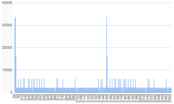
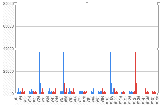
  • 2 (bytes for unsigned int) * 14 (buttons to encode) * 255 (max number of time intervals stored) = 7140 bytes!!! per set (even only 2 sets requires 14.3KB of memory)
  • The example code stores the info by using a timer to receive, store and repeat the time interval between 2 "highs" & "lows" --> Q1: Is there another way to store this information and thus reduce the storage required?

Main Q: How should I "increase" the memory available for my needed storage?

I have thought of several workarounds, some of which I have tried and failed (and am thus asking for help here):

1. Move some of the program memory to RAM or Flash

This was one of the first things I tried to do - but I can't fully understand the documentations on the linker files.

  • So far I've been able to move everything except my codes, constants and persistent pragmas originally in FRAM to RAM, saving a miniscule 60 bytes.
  • Trying to move code to RAM causes "program will not fit into available memory" error. (according to memory allocation, .text is a total of about 3.3kB)
  • Trying to move constants to RAM compiles but causes ISR_traps
  • I've tried to move .text and .const to Flash instead, as per other forum's suggestions, but FR4133 doesn't seem to have Flash memory?

--> Q2: How can I successfully partition away some of my code (.text, .const) to either RAM or Flash?


2. Alternative way of storing the information/compressing the IR information

At first I thought I could reduce the information by almost 1/4 because I had assumed 255 counts is overkill and only unsigned char was necessary to store the time intervals. 

Turns out after testing using A/C signals, I was wrong - somehow both are necessary.

--> Q3: Are there other ingenious ways of compressing, storing or representing the necessary IR information that I haven't thought of?


3. Using another MSP430 as "external storage"

This is a method I can actually envision working, but haven't tried out. 

--> Q4: Is it possible to communicate and transfer FRAM information between 2 similar MSP430s via SPI or I2C?


4. SD card boosterpack

Last resort, overkill and might not be compatible with the BOOST-IR boosterpack (it takes up all the male header pins)

Thank you for your help in advance!

Samuel

  • Hi Samuel,

    Let me address your workarounds...

    1. Move some of the program memory to RAM or Flash

    You really can't do this. I don't believe that chip has flash at all. You have FRAM and RAM. (Though the FRAM is a great substitute for flash.) You can run code in RAM, but where does that code come from? The debugger can put it there temporarily, until you power off. You can copy it there from FRAM on every boot, but that doesn't save you any FRAM. RAM is already being used for all of your runtime variables by default. That's the best you can do in terms of minimizing FRAM utilization. Everything in .text and .const must reside somewhere non-volatile.

    2. Alternative way of storing the information/compressing the IR information

    I'm not entirely clear on what is going on here. Does it use unsigned long by default and you are trying to truncate to unsigned char? If so, what is the range of the values you are seeing? And what does this have to do with A/C...?

    Will unsigned short (16 bits) provide adequate range?

    You can divide the clock feeding the timer to reduce the magnitude of the values. But this will adversely affect the granularity of your timing. Maybe that's okay and worth the trade-off.

    Update: I see. You were going to get to 1/4 by both decreasing from int to char and reducing the array size by close to half.

    3. Using another MSP430 as "external storage"

    You could do this if you had an available serial or parallel interface, but there are much better ways. This is what memory devices are for. You could get a EEPROM, flash, or FRAM device and connect that to the MSP430 for external storage. You will still need a spare interface to do that.

    If you are clever, you can use a single SPI master to talk to both the memory chip and to whatever else might be connected. That is where chip-selects come into play.

    4. SD card boosterpack

    That does seem like overkill. The interface to an SD card is SPI; not much different from using one of the memory chips mentioned above.

    Main Q: How should I "increase" the memory available for my needed storage?

    I think your best bet is to try to squeeze the information a little tighter like you have been trying to do. Otherwise you are looking at adding external memory or switching to a different MSP430 with more built-in non-volatile memory.

  • Hi Greg,

    Thanks for the reply!

    I'll focus on asking questions for the solutions which are remotely feasible...

    2. Alternative way of storing the information/compressing the IR information

    If so, what is the range of the values you are seeing? And what does this have to do with A/C (aircon)...?

    Let me explain how the IR signal "collection" and "transmission" works here ('cos I didn't really explain clearly, sorry) :

    From TI:

    While receiving signals in learning mode, the MSP430FR4133 device uses the timer capture function to record the time between signal edges for the high and low pulses. The sequence of pulse lengths is stored in FRAM for later use to generate the same signal when the button is pressed. For more details about how the learning mode software works, see Section 3.1.1.5. Note that the IR receiver and demodulator on the BoosterPack is tuned for 38-kHz carrier frequency. This is one of the most common carrier frequencies used by many remote control manufacturers for a number of devices. If communication needs to be with a device that uses a different carrier (for example, 40 kHz), this component can be replaced with a different receiver and demodulator device.

    • I have 2 arrays stored in FRAM, rx_cnt and tx_data
    • rx_cnt [TOTAL_MODES] [TOTAL_CODES]: an array for each button. It counts how many high and low pulses there are. Default is a maximum of (MAX_RX_CNT= 255), a value which I have indeed seen with my aircon remote signal (debugging mode)
    • tx_data [TOTAL_MODES] [TOTAL_CODES] [MAX_RX_COUNTS]  : This is the major problem. It stores the time between signal edges. Right now, it's unsigned int, but I want to somehow "compress" this to unsigned char. Again, doesn't look very possible since I have seen values above the unsigned char value of 255.

    You can divide the clock feeding the timer to reduce the magnitude of the values. But this will adversely affect the granularity of your timing. Maybe that's okay and worth the trade-off.

    • Sounded like a possible solution, but I'm not sure how feasible this is with the carrier frequency needing to be 38kHz.
    • Maybe there's something about the modulation that I'm missing out, and this method will be feasible

    Update: I just mucked around a bit, and realised that the IR code being "read" and "emitted" is stored differently each time (although the actual code is the same). I might want to go do some more research into the ASK modulation and see if I can store the whole IR code as a set of long integers (converted from individual bits ?? ) instead of a set of time differences.

    Update 2: After graphing the data, I noticed repeated signals for both TV and A/C signals. Remote controls have shorter pulses while A/C have longer pulses.

    It seems that I am able to perform a workaround by having the max counts for aircon signals to 255 but TV signals to less than 100. 

    Graphs are displayed below:

    Fig 1: TV signal (2 graphs of the same button)


    Fig 2: Aircon Signal

    3. Using another MSP430 as "external storage"

    I do have an extra MSP430FR4133 (it's a faulty one without male header pins cos TI screwed up the manufacturing, but I can work with it), which I might be able to use as the proposed storage.

    According to the BOOST-IR specs, the SPI ports are left unused so I think this might be the most feasible, but troublesome solution.

    External Flash and FRAM storage sounds like a possible idea (hopefully they're not too expensive).

    Greg Fundyler said:

    Hi Samuel,

    Let me address your workarounds...

    1. Move some of the program memory to RAM or Flash

    You really can't do this. I don't believe that chip has flash at all. You have FRAM and RAM. (Though the FRAM is a great substitute for flash.) You can run code in RAM, but where does that code come from? The debugger can put it there temporarily, until you power off. You can copy it there from FRAM on every boot, but that doesn't save you any FRAM. RAM is already being used for all of your runtime variables by default. That's the best you can do in terms of minimizing FRAM utilization. Everything in .text and .const must reside somewhere non-volatile.

    2. Alternative way of storing the information/compressing the IR information

    I'm not entirely clear on what is going on here. Does it use unsigned long by default and you are trying to truncate to unsigned char? If so, what is the range of the values you are seeing? And what does this have to do with A/C...?

    Will unsigned short (16 bits) provide adequate range?

    You can divide the clock feeding the timer to reduce the magnitude of the values. But this will adversely affect the granularity of your timing. Maybe that's okay and worth the trade-off.

    Update: I see. You were going to get to 1/4 by both decreasing from int to char and reducing the array size by close to half.

    3. Using another MSP430 as "external storage"

    You could do this if you had an available serial or parallel interface, but there are much better ways. This is what memory devices are for. You could get a EEPROM, flash, or FRAM device and connect that to the MSP430 for external storage. You will still need a spare interface to do that.

    If you are clever, you can use a single SPI master to talk to both the memory chip and to whatever else might be connected. That is where chip-selects come into play.

    4. SD card boosterpack

    That does seem like overkill. The interface to an SD card is SPI; not much different from using one of the memory chips mentioned above.

    Main Q: How should I "increase" the memory available for my needed storage?

    I think your best bet is to try to squeeze the information a little tighter like you have been trying to do. Otherwise you are looking at adding external memory or switching to a different MSP430 with more built-in non-volatile memory.

  • Default is a maximum of (MAX_RX_CNT= 255), a value which I have indeed seen with my aircon remote signal (debugging mode)

    Are you sure it is exactly 255 with aircon and not more perhaps?

    After graphing the data, I noticed repeated signals for both TV and A/C signals. Remote controls have shorter pulses while A/C have longer pulses. It seems that I am able to perform a workaround by having the max counts for aircon signals to 255 but TV signals to less than 100. 

    Let's clarify this. When you say longer pulses, do you mean more values in the array, or do you mean that each value stored (unsigned int) is larger?

    What is the largest stored value you have observed? Is it only slightly over 255, like 300 or 400?

    [Dividing the clock] sounded like a possible solution, but I'm not sure how feasible this is with the carrier frequency needing to be 38kHz. Maybe there's something about the modulation that I'm missing out, and this method will be feasible.

    The modulation happens outside of the MSP430. How you measure and recreate the pulses has nothing to do with that modulation. So if the measured pulses never exceed 511, then what you can do is divide the timer clock by 2. (If different timers are used to measure the pulses and to create the pulses, then you must divide both timers the same way.) Doing this will reduce your values by 2x, allowing them to fit within unsigned char.

    Of course another way to do it is to divide the value by 2 when you store it into memory and multiply it by 2 when you read it back out. But reconfiguring the timer(s) is cleaner.

    As you can imagine, when you reduce the values by 2x, you lose the information in the LSB. But as I mentioned before, this might be okay. IR has loose tolerances. On that note...

    I just mucked around a bit, and realised that the IR code being "read" and "emitted" is stored differently each time (although the actual code is the same).

    Your captured values will probably not be exactly the same every time, but should be pretty close. It is an analog-to-digital conversion of real-world time to digital clock counts. Error is to be expected.

    Changing topics to other ways to store the codes: I experimented with codes from a TV remote one time. If memory serves me right, there were two patterns: one for a low bit and one for a high bit. I determined that each button on the remote generated 32 bits this way. And so I stored each button as an unsigned long. I wrote a function to generate the appropriate timed pulses for low and high bits given a 32-bit code. That would allow you to store 14 buttons in a total of 56 bytes. But it would be specific to that kind of remote control.

    More storage space: If you need a lot of storage space, the SD card booster pack may be the way to go. It's simple in that you just stack it and don't have to solder, etc. You could even store an entire database of IR devices in it, like universal remotes do. If you need only a little more space, you could use something like this. But frankly $10 + shipping is a lot of money for 32KB these days. You could get 256KB FRAM or 128KB EEPROM in DIP packages that you can work with easily. There are a lot more options if you can work with tiny packages. Here is 256MB of flash for $5. Definitely not practical for your application though. Just giving you an idea of what is possible.

  • HI Greg, 

    Thanks so much for your help and patience...

    So I think my terms have been a little confusing (sorry).

    Let's clarify this. When you say longer pulses, do you mean more values in the array, or do you mean that each value stored (unsigned int) is larger?

    [Direct addressing of question:] I mean more (unrepeated) values in the array, ie the aircon is probably sending a 64 or 128-bit signal instead of a 32-bit one like the TV.

    [Clarification:] TX_data: An array of variable length rx_cnt. This varied length, I realised, corresponds to how much data it receives before I press "OK". Each value TX_data[ i ] contains a number from 0 to a max of 40,000 (as far as I've seen) which is the time difference as per TA0CCR0 - old_TA0CCR0. 

    When I plotted the graph of TX_data, I got this:

    AIRCON

    TV

    The graphs plots TX_data[i] (y-axis) against i (y-axis)

    Notice that there's a repeating pattern for each graph (it's less obvious for the aircon since the second repeat isn't complete)?

    The repeating pattern is "shorter" for TV: #2 to #27, #28 to #53, #54 to #79 and so on. The difference between the indexes is about 25.

    The repeating pattern is "longer" for AIRCON: #2 to #148, #149 to (..truncated..) and so on. The difference between the indexes is about 146. This was what I meant by "shorter"/"longer" pulses.

    What I suspect is that this repeating pattern is the 32/64/128-bit code the aircon and TV is sending. I plan to see if I can decode the pattern to a set of 0s and 1s. Since you've set the precedence before, I know it's probably possible, at least with the TV :)

    The modulation happens outside of the MSP430. How you measure and recreate the pulses has nothing to do with that modulation. So if the measured pulses never exceed 511, then what you can do is divide the timer clock by 2. (If different timers are used to measure the pulses and to create the pulses, then you must divide both timers the same way.) Doing this will reduce your values by 2x, allowing them to fit within unsigned char.

    Of course another way to do it is to divide the value by 2 when you store it into memory and multiply it by 2 when you read it back out. But reconfiguring the timer(s) is cleaner.

    As you can imagine, when you reduce the values by 2x, you lose the information in the LSB. But as I mentioned before, this might be okay. IR has loose tolerances. On that note...

    Dividing the clock by 2 probably won't help since the values are mostly in the order of 2,000-40,000. What I suspect is that 2,000 (for example) is 1 bit to the TV, and a value of 4,000 is around 2 bits etc. The exceedingly high 40,000 value is probably a pause before the next repeat of the same 32-bit number. 

    Your captured values will probably not be exactly the same every time, but should be pretty close. It is an analog-to-digital conversion of real-world time to digital clock counts. Error is to be expected.

    Thanks for explaining it this way... Makes sense now!

    Changing topics to other ways to store the codes: I experimented with codes from a TV remote one time. If memory serves me right, there were two patterns: one for a low bit and one for a high bit. I determined that each button on the remote generated 32 bits this way. And so I stored each button as an unsigned long. I wrote a function to generate the appropriate timed pulses for low and high bits given a 32-bit code. That would allow you to store 14 buttons in a total of 56 bytes. But it would be specific to that kind of remote control.

    Thanks! I might pursue this way since it's for my home appliances, and I can just tune to each appliance.

    Regardless, thanks a ton Greg! I'll update if I see any interesting patterns :)

  • Thank you for clarifying. That makes a lot more sense. I'm glad I have been able to be helpful so far.

    So now that I understand your graphs a bit better, let's see if we can derive some patterns. Let's start with the TV remote since that seems simpler.

    As you indicated, the repeating pattern is quite short. Let's focus on 2-25. I see a series of short and long pulses, with the long pulses being roughly double the amplitude of the short ones. Let's make the shortest pulse the basic unit of time and encode the command as a series of time intervals stored as bits. So for example, 0101 means four pulses in a row of one unit each (or 4 short pulses). And 0110010 means 1 unit, 2 units, 2 units, 1 unit, 1 unit (or short long long short short). The command can be encoded as 0110101101011010101101010101. That's only 28 bits.

    That is not a great encoding scheme. For one, the number of bits required will depend on how many long pulses you have. But this kind of scheme might be appropriate if you need to encode more than 2 types of pulses. So it would work for encoding the first 2 really long pulses as well: 0000000000000000000000001111. The entire command from 0 to 25 is then: 00000000000000000000000011110110101101011010101101010101. That's 56 bits for the whole thing and you already know to rebroadcast it several times.

    Now let's try to optimize it further. Looking at 2-25 again, let's say short pulse is 0 and long pulse is 1. You can encode the command as 010001000100000100000000. That's only 24 bits and it doesn't matter how many of the pulses are long vs short.

    How about one step further? It appears that the pulses come in pairs and the first one in a pair is always short. Let's say short-short is 0 and short-long is 1. The command is 101010010000. That's only 12 bits! And honestly, I would bet that this particular TV remote is based on 12-bit codes.

    And what about the first 2 really long pulses? They look like a sync pattern to me. I would bet that every button on the remote generates the same sync pattern. So you don't need to try to store it for every button. Just write a function that knows how to interpret a 12-bit code and generate a TX_data array from it, including the sync pattern in [0] and [1].

    You should be able to do the same thing for aircon. The pulses appear to be longer, but the principle is the same. It may be a bit more complicated because it appears that some of the pulses are very, very short. Or is that just how the graph is rendered? More likely those are glitches where the timer thought it saw the signal briefly appear or disappear when it really didn't. And unfortunately, it will faithfully reproduce those glitches on the output.

    The method of capture and reproduction via timers that is currently being employed is great for generic IR applications where you have no idea what the format is and don't care. It is terribly inefficient though.

    One more insignificant detail: If I recall correctly, TV codes are transmitted LSB-first. So the 12-bit code above is actually 000010010101. You might find that all of the buttons start with 0000, in which case it's really an 8-bit code that you can store as a single byte: 0x95.

  • Thanks again Greg for your help... It's getting clearer each time :)

    I thought it would be helpful if I provided a link to the raw numbers for the TX_data in a Google spreadsheet: https://docs.google.com/spreadsheets/d/1n5Po7JMPqhbGrt-DqBWE_TvRk053VFcgUd0s_vl1pZw/edit#gid=226443439

    Just to double clarify to see if we are on the right page... Below is a table for the TV remote data, divided by the lowest number and rounded to 1 d.p.

    #2 #3 #4 #5 #6 #7 #8 #9 #10 #11 #12 #13 #14 #15 #16 #17 #18 #19 #20 #21 #22 #23 #24 #25 #26 #27
    4.4 1 2.2 1 1.1 1 2.2 1 1.2 1 2.2 1 1.2 1 1.2 1 2.2 1 1.2 1 1.2 1 1.2 1 1.2

    16.7

    Because each entry is based on the time difference between the high and low pulses, each entry corresponds to the number of '0's or '1's and this pattern alternates. So assuming the index #2 are 4 '0's, we have:

    #2 #3 #4 #5 #6 #7 #8 #9 #10 #11 #12 #13 #14 #15 #16 #17 #18 #19 #20 #21 #22 #23 #24 #25 #26 #27
    4.4 1 2.2 1 1.1 1 2.2 1 1.2 1 2.2 1 1.2 1 1.2 1 2.2 1 1.2 1 1.2 1 1.2 1 1.2 16.7
    0000 1 00 1 0 1 00 1 0 1 00 1 0 1 0 1 00 1 0 1 0 1 0 1 0
    1111111111111111

    Is this correct? (Of course it could be 1111 0 11 and so on too, but since u say that it's LSB first, I will just assume it's like this first. I could always double check later.)

    And what about the first 2 really long pulses? They look like a sync pattern to me. I would bet that every button on the remote generates the same sync pattern. So you don't need to try to store it for every button. Just write a function that knows how to interpret a 12-bit code and generate a TX_data array from it, including the sync pattern in [0] and [1].

    The first really long pulse is probably just irrelevant data, ie just measuring how long it took before I pressed "COPY" (and started the timer) to when the TV remote control was pressed (and the MSP started receiving an IR signal).

    As for the long 16 bits at the end/start of the cycle, that could be the "sync code" you are referring to. Not sure how important the "sync code" is, but since it's repeated, I might as well replicate it anyway.


    You should be able to do the same thing for aircon. The pulses appear to be longer, but the principle is the same. It may be a bit more complicated because it appears that some of the pulses are very, very short. Or is that just how the graph is rendered? More likely those are glitches where the timer thought it saw the signal briefly appear or disappear when it really didn't. And unfortunately, it will faithfully reproduce those glitches on the output.

    Probably true regarding the glitches... didn't think of that.

    Speaking of glitches, if I divide the raw data for both the aircon and TV by the lowest number, I notice something:

    Let's look at the un-processed data for TV. 2 numbers catch my interest: 2221 and 2580 (processes down to 1 and 1.1 respectively). I was able to have 2 sets of data for the same buttons, and if you see them side by side, if one showed 2580, the other also shows 2580. 

    #2 #3 #4 #5 #6 #7 #8 #9 #10 #11 #12 #13 #14 #15 #16 #17 #18 #19 #20 #21 #22 #23 #24 #25 #26 #27 #2 #3 #4 #5 #6 #7 #8 #9 #10 #11 #12 #13 #14 #15 #16 #17 #18 #19 #20 #21 #22 #23 #24 #25 #26 #27
    9773 2221 4972 2221 2494 2324 4972 2221 2580 2222 4885 2324 2580 2221 2580 2222 4887 2325 2580 2220 2580 2221 2579 2222 2579 37113 9773 2221 4972 2221 2494 2324 4972 2221 2580 2222 4885 2324 2580 2221 2580 2222 4887 2325 2580 2220 2580 2221 2579 2222 2579 37113
    9801 2206 5012 2207 2599 2206 4994 2223 2600 2205 4993 2205 2617 2206 2598 2205 4994 2222 2598 2206 2600 2207 2599 2206 2600 37259 9801 2206 5012 2207 2599 2206 4994 2223 2600 2205 4993 2205 2617 2206 2598 2205 4994 2222 2598 2206 2600 2207 2599 2206 2600 37259

    The question is, can we consider this "2580" as just the "analog-to-digital conversion error" you mentioned in your previous reply, or is there something I'm missing out?

    One more insignificant detail: If I recall correctly, TV codes are transmitted LSB-first. So the 12-bit code above is actually 000010010101. You might find that all of the buttons start with 0000, in which case it's really an 8-bit code that you can store as a single byte: 0x95.

    Not so insignificant after all, since this could really help compress the code further and let me know whether it starts with 0000 or 1111. 

    Thanks again,
    Samuel
  • I think you're on the right track. The exact numbers don't matter. There is a lot of wiggle room. Since the long pulses are double the length of the short pulses, your timing has to be off by a lot to screw it up. How much variation can your eye tolerate and still be able to differentiate short pulses from long pulses? The TV can probably tolerate that much too.

    The difference between the numbers is a combination of your analog-to-digital conversion error and the remote control's digital-to-analog conversion error. With that much variation it's probably a safe bet that the remote does not have a reliable oscillator. Probably just a simple RC (resistor-capacitor) oscillator that varies with temperature, the phase of the moon, and what you had for breakfast this morning.

    So I wouldn't focus on 2580 or 2221. I would average all the short pulses together from several samples and use that as your basic unit of time. I would also lean toward using the 12-bit encoding (or even 8-bit if my theory proves out) as it is much more predictable and easier to implement than the scheme you picked. But the one you picked is more flexible. It's up to you.

    If you want to confirm me as a collaborator on your Google Sheets document I would be happy to help you there.
  • Hi Greg,

    I've just given you edit access...

    Unfortunately I can't work on the code much till Saturday, thanks to national military service (sigh) commitments. Hopefully I'll still be able to think about the data processing though!

    Samuel

**Attention** This is a public forum