Part Number: MSP430F5438A
Hello,
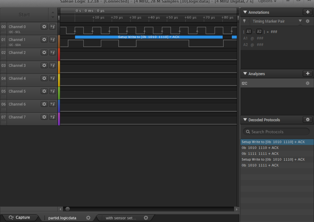
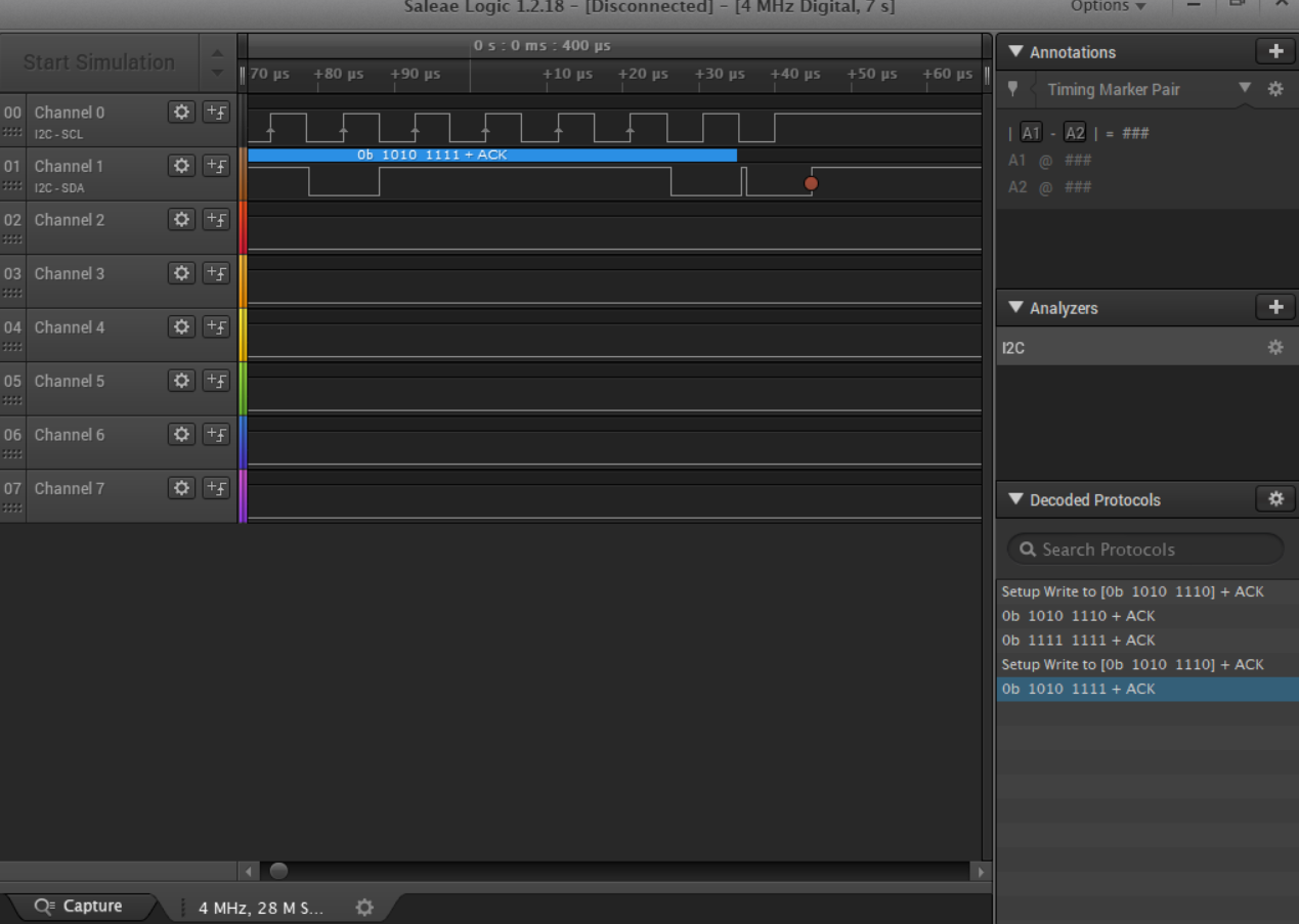
I am trying to communicate with the MAX30101 sensor through an I2C protocol. Here the master is MSP430F5438A, and my IDE is Code Composer studio. From the sensor, I am trying to get how many samples I have to read. I am building the code from scratch. For my purpose, I have to read the WR_PTR and RD_PTR data fro sensor. I'm supposed to get some value in between 1 to 32, but I am always getting 0 for both. Anyone can answer is my I2C code section is correct or not? If not how can I fix it?
Following is the datasheet of the sensor (If necessary):
datasheets.maximintegrated.com/.../MAX30101.pdf
My Code:
void Clock_setup(){
P11DIR |= BIT2; // check smclk, 1MHz default
P11SEL |= BIT2; // check smclk, 1MHz default
P11DIR |= BIT0; // check aclk, 32.8KHz default
P11SEL |= BIT0; // check aclk, 32.8KHz default
}
void I2C_setup() {
P3SEL |= BIT7; // P3.1(UCB0_SDA), P3.2(UCB0_SCL) // 3.7 UCB1_SDA, 5.4 UCB1_SCL
P5SEL |= BIT4;
UCB1CTL1 |= UCSWRST; // reset enable
UCB1CTL0 = UCMST + UCMODE_3 + UCSYNC; // master + I2C mode + Sync
UCB1CTL1 = UCSSEL_2 + UCSWRST; //use SMCLK + still reset
UCB1BR0 = 10; // default SMCLK 1M/10 = 100KHz
UCB1BR1 = 0; //
UCB1I2CSA = MAX30101_I2C_ADDRESS; // MAX30101 7 bit address 0x57
UCB1CTL1 &= ~UCSWRST; // reset clear
// UCB1IE |= UCTXIE + UCRXIE; //TX and RX interrupt enabled
}
void MAX30101_setup(){
sendByte(0x08, 0x40); // Sample avg.=4
sendByte(0x09, 0x07); // Mode= Multi
sendByte(0x0A, 0x0F); //ADC range= 2048, sample rate=400, PW control=411
sendByte(0x0C, 0x1F); // RED pulse amplitude
sendByte(0x0D, 0x1F); // IR pulse amplitude
sendByte(0x0E, 0x1F); // GREEN pulse amplitude
sendByte(0x10, 0x1F); // Proximity pulse amplitude
sendByte(0x11, 0x77); // SLOT 01 and 02
sendByte(0x12, 0x07); // Slot 03
FIFO_Clear();
}
void FIFO_Clear(){
sendByte(0x04, 0x00); // FIFO WR_PTR clear
sendByte(0x05, 0x00); // FIFO over flow counter clear
sendByte(0x06, 0x00); // FIFO RD_PTR clear
}