Part Number: MSP430F2252
Other Parts Discussed in Thread: MSP-FET, , PMP8740, UNIFLASH
Dear Sir/Madam,
I have installed code composer studio (CCS) version ( Version: 8.1.0.00011) & purchased MSP-FET
Flash Emulation Tool for MSP430F2252 controller programming.
Q1) Controller - MSP430F2252 & I am using PMP8740 Rev_C PCB (2KW Battery Charger Module).
I enabled MSP430 hex facility, Intel hex and generate hex file using ccs IDE --> PMP8740 Rev_C.hex, correct?
Q2) How to select MSP-FET Flash Emulation Tool in code composer studio (CCS) for hex programming?
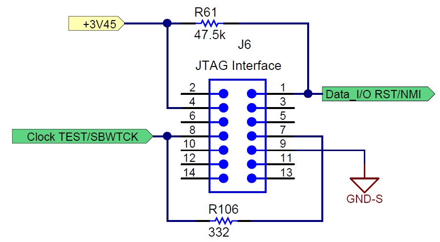
Q3) How to select 2 wire JTAG Interface in code composer studio (CCS) for hex programming? Please find attached
jpg file of 2-wire JTAG Interface(14-Pin connector).
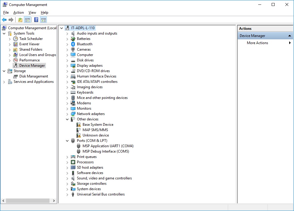
Q4) When I connected MSP-FET Flash Emulation Tool to Laptop, appeared two com port on Laptop Device Manager. (MSP Application UART1(com4) & MSP Debug Interface(com5)
Which one is used for hex programming? Please find attached jpg file of Device Manager.