This thread has been locked.

If you have a related question, please click the "Ask a related question" button in the top right corner. The newly created question will be automatically linked to this question.

MSP-FET: MSP430F2xx firmware download using BSL

Part Number: MSP-FET

Good morning.

I'm trying to use MSP-FET to download a firmware on a MSP430F2xx family microcontroller via bootstrap loader pins: BSL TX, BSL RX, TCK and RST/NMI

MSP-FET                              MCU (F2xx)
UART_CTS (10)    <---->    (58) RST\NMI
UART_TXD (12)    <---->    (13) BSL transmit
UART_RTS (13)    <---->    (57) TCK (Test clock - JTAG)
UART_RXD (14)    <---->    (22) BSL receive

The connection was made using simple wires (pin to pin), no extra hardware.

I have tried using BSLDEMO2 command lines, but without success. It didn't generate hardware BSL invocation like described on SLAU319T. I also tried to use Putty do change port baud rate configuration from 9600 to 9601, no success too. I also tried to open COM port conection and after COM was open, changing baud rate to 9601. No sucess.

I would like to know if it is possible to use MSP-FET to download to F2xx family using BSL connection?

Besides that, if there is any other software (with GUI would be great!), that I can use to stablish this kind of connection with F2xx family?

Thanks in advance.

  • Hello Leonardo,

    Unfortunately, we do not have GUI support for the older BSL devices as of yet. That being said, I believe i know the cause of your issue. Your connections to the MSP-FET are not correct. for proper BSL invocation, the RST and TST lines on the MSP430 need to be connected to the TEST (Pin 8) and RST (Pin 11) pins on the MSP-FET. You will also need a shared ground as well, and VCC connection depending on your power setup when programming. For more information, please see Table 3 and Section 4.2 in the BSL Scripter User Guide, www.ti.com/lit/slau655 .

    Note: the user guide linked above is for the BSLScripter SW that does not support our older devices. the BSLDemo2 SW supports the older parts. That being said, the general connection information contained in the section pointed to is relevant for both programs.
  • Hello Jace,

    Thanks for your answer.

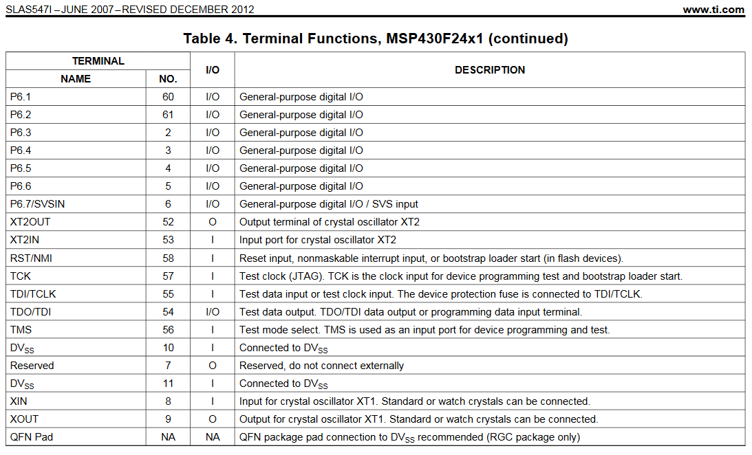
    I tried to change pins connection as you suggested but still no success. The MCU I'm using don't mention a pin with name TEST (literally). Please see below the list os pins that have test on its name:

    I tried to connect MSP-FET pin 8 to pins 57 (TCK) and 56 (TMS). Both gave me the same behavior: MCU resets but didn't go to BSL, instead it goes to its normal functioning, like a normal reset.

    One thing that I forget to mention is that the programming fuse is blowed. We are trying to update our firmware on boards that was on stock.

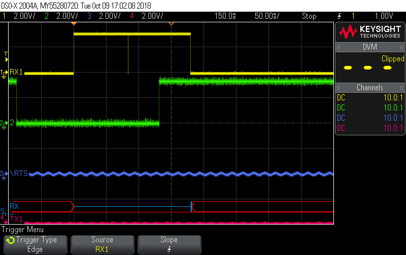
    Please also take a look on RST and TEST signal from MSP-FET when I open UART1 COM port using baud rate 9601.

    The signals appear to be in accordance with that described in BSL User Guide.

    Do you have any other clue?

    When the fuse is blowed, the MCU is still able to initiate on bootstrap mode?

    Thanks in advance.

  • Leonardo,

    Ah, you are using a device with dedicated JTAG pins and thus no TEST pin. In that case, please see section 1.3.1.2 in the Flash BSL User Guide (http://www.ti.com/lit/slau319 ). In this case the TCK pin is used for BSL entry instead of TEST (as its non-existent).

    So your connections are going to be RST -> RST, TCK -> TCK and the appropriate UART connections between the MSP-FET and the MSP430.
  • Table 1 of slau319t.pdf shows that your f2xx part can be flashed with MSP-FET, but the software required is BSLDEMO2.  Also, if your part has a TCK pin, but not a TEST pin, then the pattern which must be transmitted to /RST and TCK is shown in Figure 3 of that pdf, not figure 2.

    I've never tried the combination of BSLDEMO2 and MSP-FET, and don't know how you get MSP-FET to generate the correct pattern, if that's even how it works.  Actually, BSLDEMO2 generates a pattern on its own, so  if DTR and RTS flow through the MSP-FET to its /RST and TCK  outputs, it might work.  You would need to see if the scope traces match Figure 3.

    If the traces are right except that the polarity of one or both lines is wrong, you may want to try a version of BSLDEMO that I compiled from the TI source code which adds options -i and -j to invert the polarity of DTR and/or RTS, respectively.

    https://github.com/gbhug5a/MSP430-BSL/tree/master/BSLDEMO-2.01c/Executable

  • Hi Jace,

    Thank you again.

    The problem was the pin connection. After making the correct connection, the procedure using TeraTerm also works!

    For further reference about this issue:

    1) BSL connection for F2xx family:

    MSP-FET MCU (F2xx)
    TCK (07) <----> (57) TCK (Test clock - JTAG)
    RST (11) <----> (58) RST\NMI
    UART_TXD (12) <----> (13) BSL transmit
    UART_RXD (14) <----> (22) BSL receive

    Literature reference: please see section 1.3.1.2 in the Flash BSL User Guide (http://www.ti.com/lit/slau319 )

    2) BSL Invocation for F2xx family using MSP-FET

    User will need to use a serial port terminal emulator that allows to configure baud rates different from standard values. To enter BSL mode you will need tho configure baud rate as 9601 on UART1 port of MSP-FET's virtual COM ports . This will generate RST and TCK signals to put MCU on BSL mode. After that you will need to close COM port (exit terminal) and use BSLDEMO2 commands.

    Literature reference: processors.wiki.ti.com/.../f1391570252-215069158.html

    HOWEVER, still experiencing some problems. Now related with security password. Using a brand new MCU during tests, BSLDEMO2 try to send standard password (32 x FFs) but MCU didn't recognizes it and mass erase all memory.

    Another thing is that BSLDEMO2 stopped working while trying to send a valid firmware to an empty MCU. Windows message only says that application has stopped working.

    Still have some work to do...

    Thanks again!
  • Hello George,

    Good afternoon.

    Thanks for your help.

    MSP-FET didn't transmit flow control signals directly to its JTAG pins. I didn't tested it so hard, but I believe user will need to put MSP-FET on specific state where all VCP signal are transmitted to JTAG pins.

    Thanks anyway.
  • Well I don't have an MSP-FET, so I can't help with the experimenting.  But when you find a method that works for the BSLDEMO2 and MSP-FET combination, I hope you will post it here.  And if you aren't committed to using an MSP-FET, you might consider using a generic USB-to-UART adapter in combination with my version of BSLDEMO2.

  • Hi Leonardo,

    thank you for your input. Our suggestion for the MSP430F2xx bootloader, we could use a simple USB to Serial converter. The MSP-FET, as you discovered, needs a special baudrate to generate the BSL entry sequence.

    As suggestion from George, if you have a universals USB to Serial converter, BSL Demo should work.

**Attention** This is a public forum