This thread has been locked.

If you have a related question, please click the "Ask a related question" button in the top right corner. The newly created question will be automatically linked to this question.

MSP430L092: programming limitations

Other Parts Discussed in Thread: MSP430L092


I have a few questions about the new line of low voltage MSP430L092 and MSP430C091/2.

http://processors.wiki.ti.com/index.php/Low_Voltage_Microcontrollers_from_MSP430


This seems like very exciting product. In my research on enhanced RFID tags we are wirelessly powering MSP430s, and using them to explore sensor and computation enhanced RFID applications. ( http://wisp.wikispaces.com/). Thus a lower voltage MCU would be of great benefit.


However, it appears that the L092 has several short coming that will make intolerable for use by the wider MSP430 community.

  1.  First the L092 requires external EEPROM, boost converter, and level shifters.
  2. Second the MSP430C091/2 will be Mask ROM programmable only.


The following excerpts from the “L092 Introduction” slide show help explain some of these choices. http://www.ti.com/ww/en/mcu/multimedia/L092_Introduction/


“The flash technology is not a practical choice for ultra low voltage operation” - Dung Dang

I believe Dung states this because Flash Memory needs a rather high voltage for writing/erasing. For example the MSP430XF line requires 2.2v for a flash write/erase and uses a on-chip charge pump to kick the voltage up to ~15 volts (at nano-amp currents). I can see why it would be impractical to kick 0.9 volts up to 15 volts for on the fly memory storage.

However, what about using flash only for programming so we do not have to use an external ROM, boost converter, and level shifters? Basically, this is how many engineers use the current MSP430 line. We program the MSP430 at 2.2v, and run it at 1.8v.

“Hence the optimized memory solution is to use RAM and ROM for the L092 family. Specifically the variant with the RAM only memory can be used during development or prototype. And once moving on to production, when the firmware is finalized, it can be stored into the ROM mask, in the ROM variant, the MSP430CO92, for mass production.”


 “The L092 requires a non-volatile SPI memory external to the device to retain the firmware for the L092. Upon startup the L092 would boot the SPI memory IC and retrieve the firmware for its operation.” - Dung Dang


It seems to me that most users will never benefit for the native ROM.  We would have to deploy tens of thousands of devices to justify the cost and hassle of having TI burn the ROM for us.  Secondly there is no way to get an accurate sense of startup condition for the CO92 if we can only dev on the L092 which requires a lot of extra components.

 “Mask ROM (MROM) is a type of read-only memory (ROM) whose contents are programmed by the integrated circuit manufacturer (rather than by the user)” -http://en.wikipedia.org/wiki/Mask_ROM


My questions boil down to:

  1. Does TI intend to offer a 0.9v device that can be programmed (repeatedly) without the use of external components?
  2. Is there any chance of getting a F092 variant even if memory is only usable at the time of programming? 


Thanks,

asample


  • "Intend" is easy. Doing it is difficult. Current crop of Flash used by TI does not work at 0.9V even for read operation.

  • So that really does not answer my questions...

    I agree that it is difficult. Thankfully engineers get paid a lot of money to make difficult things possible.

    TI could integrate Flash plus a 0.9-1.8 volt charge pump just for reading memory. Thus eliminating the awkward 2+ chip solution required for the L092. They could magically come up with Flash that takes less voltage to read. There are probably lots of solutions.  

    My question is: Is there a path forward? or is the external EEPROM plus boost converter the best we are going to get?


    -a

  • What  U  doubt   is  just  I doubt . 3Q    .

    besides, i have spent 2 days on how to emulate  L092 with the Development Tool that Ti provide,but it syill don't work.

    Anyone can give some advices ? it would be appreciative..

    from China

  • Alanson,

    good questions, and thanks for your interest in the MSP430L092. 

    The reason for not incorporating a charge-pump & flash for the L092 was to eliminate any efficiency lost due to power conversion. Additionally, the analog peripheral also works natively across this voltage range. I do agree that the 2-chip solution for the L092 is a bit awkward and makes it a bit harder to realize the final product if you intend to go with the ROM part, C092. Nonetheless, different options to download/debug and emulate the C092 memory map should make the development process much easier and hopefully very close to the final version. Additionally, even with the final prototype, you can still use an L092 without the external EEPROM to thoroughly test and verify your application before releasing the ROM mask. 

    To address your other questions, we are always considering various options for the next families in the low-voltage domain such as non-volatile 0.9V memory, or other memories at different low-voltage nodes. While native low-voltage operation was the focus in the first product, other approaches (such as charge pumps, memories, etc.) are also taken into consideration. And your inputs definitely help define & shape those future products. We will share more information with you once these ideas become materialized.

    In the meanwhile, if you have a great application that can utilize low-voltage features, please do not be deterred away by the new but not too different development platform.


    Thanks & Regards,


    Dung                                                                                                                                                                                        

  • Benny,

    could you please give us some more details on what you're doing and what the problem is?


    Thanks,

    Dung

  • I  really appreciate for your reply.
     
    My English is quite bad,I do my best to express it clearly.
    We are now developing a product whose supply voltage is 1.5V,so we pay a great interest on L092。
     
    I prepared two questions for U,and hope U can do me a favor.
     
    1st.  Is The application code downloaded to EEPROM by FET430-UIF directly?
     
    As I know ,the MSP430L092 doesn't consist of any Memory(such as ROM or Flash )for User code,and the user code must be download into the external EEPROM,so how or in what way ?By the UIF?
     
    2nd.how to Emulate my code with the Development Tool that TI provided?
     
     I have fixed the Jumper in the TargetBoard MSP-TS430L092 and the L092 Active    cable according to 《MSP430 Hardware Tools User's Guider》(slau278e).
     
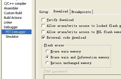
     Because of the Net problem,I can't upload all  the screenshots of My IAR (V5.10)configuration .I chose the one which I 
    think is the most important.
     I don't know if my fault configuration lead to the failed emulation ,So could U give  me some ideas on the IAR  onfiguration or other factors which will help sovle the problem.
     
     
    Thank you very much.
    //=============================================================================
     
     
    Example code from TI 。
     
    /****************************WDT Toggle Port Pin *********************************/
    /*Toggle P1.0 using software timed by WDT ISR                                    */ 
    /*                                                                               */
    /*                                                                               */
    /*                               +----L092---+                                   */
    /*                               |*1      14 |                                   */
    /*                               | 2      13 |                                   */
    /*                               | 3      12 |                                   */
    /*                               | 4      11 |                                   */
    /*                               | 5      10 |                                   */
    /*       P1.0 -Toggle Output  <- | 6       9 |                                   */
    /*                               | 7       8 |                                   */
    /*                               +-----------+                                   */
    /*                                                                               */
    /*  D. Dang, D.Archbold                                                          */
    /*  Texas Instruments Inc.                                                       */
    /*  Built with IAR Version                                                       */
    /*********************************************************************************/
    #include "msp430x09x.h"
    void main(void)
    {
        WDTCTL = WDTPW + WDTHOLD;
        
        P1DIR |= BIT0;                        // Set P1.0 to output direction
        P1OUT |= BIT0;                        // Output high on P1.0
        /************************/
        /* Setup CCS            */
        /* ACLK = VLO           */
        /* MCLK = HFCLK/8       */
        /************************/
        CCSCTL0 = CCSKEY;                 // Unlock CCS
        CCSCTL4 |= SELA_1;                // Select LFCLK/VLO as the ACLK source          
        CCSCTL5 &= ~DIVA_5;             // Divide fACLK by 4
        CCSCTL0_H |= 0xFF;                // Lock CCS
        /* Lock by writing to upper byte */
        
        
        WDTCTL = WDT_ADLY_16;                 // WDT SMCLK Delay Interval specify                  
        SFRIE1 |= WDTIE;                      // Enable WDT interrupt
        
        __bis_SR_register(LPM0_bits + GIE);   // Enter LPM0 w/ interrupts enabled
    }
    // Watchdog Timer interrupt service routine
    #pragma vector=WDT_VECTOR
    __interrupt void watchdog_timer(void)
    {
        P1OUT ^= BIT0;                          // Toggle P1.0 using exclusive-OR
    }
     
  • Benny,

    1. When debugging the L092, you can download the code into the L092 RAM [dedicated RAM for application code, called LRAM] and the device will run/be debugged as long as power is applied [RAM is volatile]. Uncheck the 'External Code Download" checkbox [shown in your screenshot] to instruct download to RAM.

    Alternatively, you can download the code into the EEPROM [non-volatile memory], which retains the firmware after power out. The flow for this option is as follows. The MSP430USB-FET controls the L092 via JTAG, and uses the device's PWM pins & shared JTAG pins to power up the EEPROM and enable SPI communication. So in a way, it is an indirect path from the PC to L092 to EEPROM when it comes to firmware downloading into the EEPROM. The settings that you have [shown in the screenshot] are correct  for this option.

    During this code download process, you might notice the LEDs will blink a few times, indicating the power converter and/or SPI communication at that time.


    2. Once you download the code into the L092 RAM or into the EEPROM, the IDE (in your case, IAR) will retain the control of the device, allowing you to start debugging your application. You can use the code example that you selected to test the function of the device.

    Hope that helps!

    ~Dung 

  • Hi Dung,

    I have solved my problem. It 's not because of my incorrect IAR configuration, in contrast,I  guess it  should be a bug of L092 in different bath or chip version.

    in Engineering samps,XL092  REV A ,I can suceed in debuggering the code with the Development Tool (TI provided).however, if I use L092 REV D, I 'll failed.

    The most interesting thing is that if I first debugger a code in a XL092(REV A) ,then i can also succed in download the code into  L092 REV D, can U help explain

    this?

    Thanks.

    -----Benny

  • Benny,

    sorry for the super late response. This thread got buried in the E2E forum and just by sheer coincidence that I found it again. 

    We have seen the behavior replicated in a similar situation where a Rev.D device has to trick the USB FET before download/debug can be started. We're still currently investigating the issue and I will update once we have more information or find a solution.


    Thanks & Regards,

    Dung

  • A late replay (I diodn't follow this thread earlier) but since it was brought to my attention again...


    What about poviding a small boot rom and flash (with charge pump) and at startup the boot rom will copy the content from flash to ram (like a C startup code copies the init values for variables) and then the flash (and the charge pump) are deactivated and the code runs from ram alone. It would combine all advantages and omit the disadvantages.

  • Well no "it would not omit all the disadvantages".

    1) Now you need a multi-part solution.

    2) The power profile will total be screwed up.

    The startup current for a boost converter will be high compared to a true native 0.9v MCU solution. Also the efficiency of boost converter is low, especially at startup.


    It would have been great if TI was upfront about the advantages AND limitation of the MSP430L092. For most applications a boost converter is a ok option. You only really deal with the startup issue when you replace the battery. However other applications that have no batteries (such as power harvesting) this is an intolerable situation.

  • alanson said:
    1) Now you need a multi-part solution.

    ??? I meant included into the chip. Like a solid-state-disk to boot from (and then unused).

    alanson said:
    2) The power profile will total be screwed up.

    Yes. If you cannot bear it, don't use it. You cannot eat the cake and keep it. :)
    However, having an external flash will show the same behavior, just that it also requires the external chip and the connections.

    It would, however, allow an easier manufacturing process: for the development, the device with 'boot flash' is used, and once it is working in the target (maybe wiht the help of a temporary additional power supply at startup), you can go and order the mask-programmed version, which does not have flash but mask rom instead and no startup copy mechanism.

    Sure, the flash version needs more ram (as much additional ram as there is flash) and likely consumes a bit more power then, but if you can satisfy this, then the device will work even better with the ROM version.

    The biggest disadvantage ATM is that the development version requries external chips for storing the program. This also means that there are datalines required and therefore development can't take place on the real target board.

**Attention** This is a public forum