This thread has been locked.

If you have a related question, please click the "Ask a related question" button in the top right corner. The newly created question will be automatically linked to this question.

MSP430FR2153: Uart drivers

Part Number: MSP430FR2153
Other Parts Discussed in Thread: MSP430FR2355, MSP430WARE

Hello,

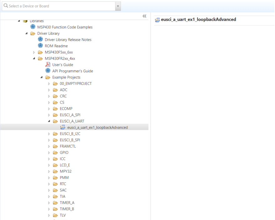
           I am looking for uart drivers for msp430fr2153 and msp430fr2355. I have gone through resource explorer in ccs v8.2 I have found only the user guide for drivers, but I haven't found any examples on the driver.

B.R.

Gourav

  • Hello Gourav,

    not sure where you have been looking for it, but e.g. under MSP430Ware -v:3.80.05.04 >> Libraries >> Driver Library >> MSP430FR2xx_4xx >> Example Projects >> EUSCI_A_UART you can find a driver lib example.

    You can find further examples on e.g. register level following the device path in MSP430Ware. MSP430Ware -v:3.80.05.04 >> Devices >> MSP430FR2xx_4xx >> device name ...

    Best regards

    Peter

  • Hello,

    please, check this example: dev.ti.com/.../
    or go to other MCU430 family to look for other examples.
  • Hello Peter,
    I am intended to use 2 uart's, So does this driver support use of 2 uart's for both the msp430fr2153 and msp430fr2355 controllers.
    B.R.
    Gourav
  • Yes it does.

    Recently I experimented with FR2355 and a ROM based Driver Library as the prerequisite for a bigger project I work with.

    Two separate UART transmit channels (Tx) were set up with two different baudrates.

    I tested this with 24MHz nad 16MHz MCLK respectively and  SMCLK was used as both BRCLK sources.

    Please find below a test program.

    #include    "driverlib.h"
    #include    "rom_driverlib.h"
    
    #define     CS_MCLK_KHZ         24000
    
    #define GPIO_PORT_UCA0TXD       GPIO_PORT_P1
    #define GPIO_PIN_UCA0TXD        GPIO_PIN7
    #define GPIO_FUNCTION_UCA0TXD   GPIO_PRIMARY_MODULE_FUNCTION
    #define GPIO_PORT_UCA0RXD       GPIO_PORT_P1
    #define GPIO_PIN_UCA0RXD        GPIO_PIN6
    #define GPIO_FUNCTION_UCA0RXD   GPIO_PRIMARY_MODULE_FUNCTION
    
    #define GPIO_PORT_UCA1TXD       GPIO_PORT_P4
    #define GPIO_PIN_UCA1TXD        GPIO_PIN3
    #define GPIO_FUNCTION_UCA1TXD   GPIO_PRIMARY_MODULE_FUNCTION
    #define GPIO_PORT_UCA1RXD       GPIO_PORT_P4
    #define GPIO_PIN_UCA1RXD        GPIO_PIN2
    #define GPIO_FUNCTION_UCA1RXD   GPIO_PRIMARY_MODULE_FUNCTION
    
    
    void    CS_clockInit (void)
    {
        ROM_CS_turnOnXT1LF( CS_XT1_DRIVE_3 );
    
    #if     ( CS_MCLK_KHZ > 16000 )
        FRAMCtl_configureWaitStateControl(FRAMCTL_ACCESS_TIME_CYCLES_2);
    #elif   (CS_MCLK_KHZ > 8000)
        FRAMCtl_configureWaitStateControl(FRAMCTL_ACCESS_TIME_CYCLES_1);
    #endif
    
        ROM_CS_initClockSignal ( CS_FLLREF, CS_REFOCLK_SELECT, CS_CLOCK_DIVIDER_1 );
        CS_initFLLParam CSparam = {0};
        CS_initFLLCalculateTrim( CS_MCLK_KHZ, ((uint16_t) CS_MCLK_KHZ/32.77), &CSparam );
    
        ROM_CS_clearAllOscFlagsWithTimeout(1000);
    }


    void    inline  CS_SMCLKinit (void)
    {
        ROM_CS_initClockSignal( CS_SMCLK, CS_DCOCLKDIV_SELECT, CS_CLOCK_DIVIDER_2 );
    }


    void    inline  XT1_GPIOinit(void)
    {
        ROM_GPIO_setAsPeripheralModuleFunctionInputPin(
            GPIO_PORT_P2, GPIO_PIN6 + GPIO_PIN7, GPIO_SECONDARY_MODULE_FUNCTION );
    }
    
    
    void    inline  UCA0UART_GPIOinit(void)
    {
        //Configure UART pins
        GPIO_setAsPeripheralModuleFunctionInputPin(
            GPIO_PORT_UCA0TXD,
            GPIO_PIN_UCA0TXD,
            GPIO_FUNCTION_UCA0TXD
        );
        GPIO_setAsPeripheralModuleFunctionInputPin(
            GPIO_PORT_UCA0RXD,
            GPIO_PIN_UCA0RXD,
            GPIO_FUNCTION_UCA0RXD
        );
    }


    void    inline  UCA1UART_GPIOinit(void)
    {
        //Configure UART pins
        GPIO_setAsPeripheralModuleFunctionInputPin(
            GPIO_PORT_UCA1TXD,
            GPIO_PIN_UCA1TXD,
            GPIO_FUNCTION_UCA1TXD
        );
        GPIO_setAsPeripheralModuleFunctionInputPin(
            GPIO_PORT_UCA1RXD,
            GPIO_PIN_UCA1RXD,
            GPIO_FUNCTION_UCA1RXD
        );
    }
    
    
    void    EUSCI_A0_UARTinit (void)
    {
        //Configure UART0
        //SMCLK = 12MHz, Baudrate = 57600
        //LSBfirst, PARITY no, STOP_BITS one
        //UCBRx = 13, UCBRFx = 0, UCBRSx = 0x25, UCOS16 = 1 (overSampling = 1)
        EUSCI_A_UART_initParam param = {0};
        param.selectClockSource = EUSCI_A_UART_CLOCKSOURCE_SMCLK;
        param.clockPrescalar = 13;
        param.firstModReg = 0;
        param.secondModReg = 0x25;
        param.parity = EUSCI_A_UART_NO_PARITY;
        param.msborLsbFirst = EUSCI_A_UART_LSB_FIRST;
        param.numberofStopBits = EUSCI_A_UART_ONE_STOP_BIT;
        param.uartMode = EUSCI_A_UART_MODE;
        param.overSampling = EUSCI_A_UART_OVERSAMPLING_BAUDRATE_GENERATION;
    
        if (STATUS_FAIL == ROM_EUSCI_A_UART_init(EUSCI_A0_BASE, &param)) {
            //return;
        }
        //EUSCI_A_UART_disableInterrupt(EUSCI_A0_BASE,EUSCI_A_UART_TRANSMIT_INTERRUPT);
        ROM_EUSCI_A_UART_enable(EUSCI_A0_BASE);
    
        ROM_EUSCI_A_UART_clearInterrupt(EUSCI_A0_BASE, EUSCI_A_UART_TRANSMIT_INTERRUPT);
        ROM_EUSCI_A_UART_enableInterrupt(EUSCI_A0_BASE, EUSCI_A_UART_TRANSMIT_INTERRUPT);
    }


    void    EUSCI_A1_UARTinit (void)
    {
        //Configure UART0
        //SMCLK = 12MHz, Baudrate = 19200
        //LSBfirst, PARITY no, STOP_BITS one
        //UCBRx = 39, UCBRFx = 1, UCBRSx = 0x00, UCOS16 = 1 (overSampling = 1)
        EUSCI_A_UART_initParam param = {0};
        param.selectClockSource = EUSCI_A_UART_CLOCKSOURCE_SMCLK;
        param.clockPrescalar = 39;
        param.firstModReg = 1;
        param.secondModReg = 0x00;
        param.parity = EUSCI_A_UART_NO_PARITY;
        param.msborLsbFirst = EUSCI_A_UART_LSB_FIRST;
        param.numberofStopBits = EUSCI_A_UART_ONE_STOP_BIT;
        param.uartMode = EUSCI_A_UART_MODE;
        param.overSampling = EUSCI_A_UART_OVERSAMPLING_BAUDRATE_GENERATION;
    
        if (STATUS_FAIL == ROM_EUSCI_A_UART_init(EUSCI_A1_BASE, &param)) {
            //return;
        }
        //EUSCI_A_UART_disableInterrupt(EUSCI_A0_BASE,EUSCI_A_UART_TRANSMIT_INTERRUPT);
        ROM_EUSCI_A_UART_enable(EUSCI_A1_BASE);
    
        ROM_EUSCI_A_UART_clearInterrupt(EUSCI_A1_BASE, EUSCI_A_UART_TRANSMIT_INTERRUPT);
        ROM_EUSCI_A_UART_enableInterrupt(EUSCI_A1_BASE, EUSCI_A_UART_TRANSMIT_INTERRUPT);
    }
    
    const   uint8_t     TXbuffer0[40] = "UART0 sample message 57600\n\r";
    const   uint8_t     TXbuffer1[40] = "UART1 sample message 19200\n\r";
    volatile    uint8_t     UART0_byteCounter = 0;
    volatile    uint8_t     UART1_byteCounter = 0;
    
    
    int main(void) {
    
        ROM_WDT_A_hold(WDT_A_BASE);
        XT1_GPIOinit();
        UCA0UART_GPIOinit();
        UCA1UART_GPIOinit();
        ROM_PMM_unlockLPM5();
    
        CS_clockInit();
        CS_SMCLKinit();
    
        EUSCI_A0_UARTinit();
        EUSCI_A1_UARTinit();


    __bis_SR_register(GIE);     //Enable interrupts
    
        while (1)
        {
            if ((UART0_byteCounter == 0) && (UART1_byteCounter == 0))
            {
                __delay_cycles(200000);
                UART0_byteCounter = 1;              //UART0 transmission init
                UCA0TXBUF = TXbuffer0[0];           //UART0 transmission init
                UART1_byteCounter = 1;              //UART1 transmission init
                UCA1TXBUF = TXbuffer1[0];           //UART1 transmission init
            }
    
            __bis_SR_register(LPM3_bits);         //Enter LPM3 (standby)
        }
    }


    #pragma vector=USCI_A0_VECTOR
    __interrupt
    void EUSCI_A0_ISR(void)
    {
        switch(__even_in_range(UCA0IV,USCI_UART_UCTXCPTIFG))
        {
            case USCI_NONE: break;
            case USCI_UART_UCRXIFG: break;              //Receive buffer full
            case USCI_UART_UCTXIFG:                     //Transmit buffer empty
            {
                if (TXbuffer0[UART0_byteCounter] != 0)
                    {
                        UCA0TXBUF = TXbuffer0[UART0_byteCounter];
                        UART0_byteCounter++;
                    }
                else
                {
                    UART0_byteCounter = 0;
                    __bic_SR_register_on_exit(LPM3_bits);
                }
    
            }
                break;
            case USCI_UART_UCSTTIFG: break;             //Start bit received
            case USCI_UART_UCTXCPTIFG: break;           //Transmit complete
        }
    }


    #pragma vector=USCI_A1_VECTOR
    __interrupt
    void EUSCI_A1_ISR(void)
    {
        switch(__even_in_range(UCA1IV,USCI_UART_UCTXCPTIFG))
        {
            case USCI_NONE: break;
            case USCI_UART_UCRXIFG: break;              //Receive buffer full
            case USCI_UART_UCTXIFG:                     //Transmit buffer empty
            {
                if (TXbuffer1[UART1_byteCounter] != 0)
                    {
                        UCA1TXBUF = TXbuffer1[UART1_byteCounter];
                        UART1_byteCounter++;
                    }
                else
                {
                    UART1_byteCounter = 0;
                    __bic_SR_register_on_exit(LPM3_bits);
                }
    
            }
                break;
            case USCI_UART_UCSTTIFG: break;             //Start bit received
            case USCI_UART_UCTXCPTIFG: break;           //Transmit complete
        }
    }
    

  • Hi Gourav,
    did the suggested code example help you? Do you need further support on this? If not please close the thread. Many thanks in advance.

    Best regards
    Peter
  • Hello peter,

                             Thank you for your reply,  the example code from resource explorer is helpful.

    B.R.

    Gourav

  • Hello Gourav,
    many thanks for the information. Thus I am closing the thread.

    Best regards
    Peter

**Attention** This is a public forum