This thread has been locked.

If you have a related question, please click the "Ask a related question" button in the top right corner. The newly created question will be automatically linked to this question.

MSP430F5529: MSP430F5529 clock output at PIN

Part Number: MSP430F5529


Hi All,

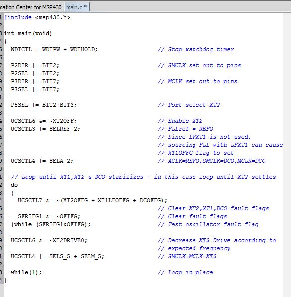
I have connected 4MHz crystal at controller's XT2 pin & 32.768KHz at XT1 and configured accordingly. If I configure SMCLK / MCLK with this 4MHz crystal the output comes with 1MHz.

void crystal_intialization(void)
{
P5SEL |= BIT4 + BIT5; //32.768KHz crystal ON 
P5SEL |= BIT2 + BIT3; //4MHz crystal ON
}

void clock_source_selection(void)
{
UCSCTL4 = SELS_5; //XT2CLK source for SMCLK 4MHz
UCSCTL5 = DIVS_0;
P2DIR |= BIT2;
P2SEL |= BIT2;

UCSCTL4 |= SELA_0;//XT1CLK source for ACLK 32.768KHz
UCSCTL5 = DIVPA_0 + DIVA_0;
P1DIR |= BIT0;
P1SEL |= BIT0;

UCSCTL4 |= SELM_5; //XT2CLK source for SMCLK 4MHz
UCSCTL5 = DIVM_0;
P7DIR |= BIT7;
P7SEL |= BIT7;
}

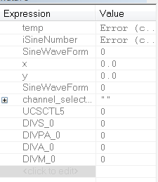
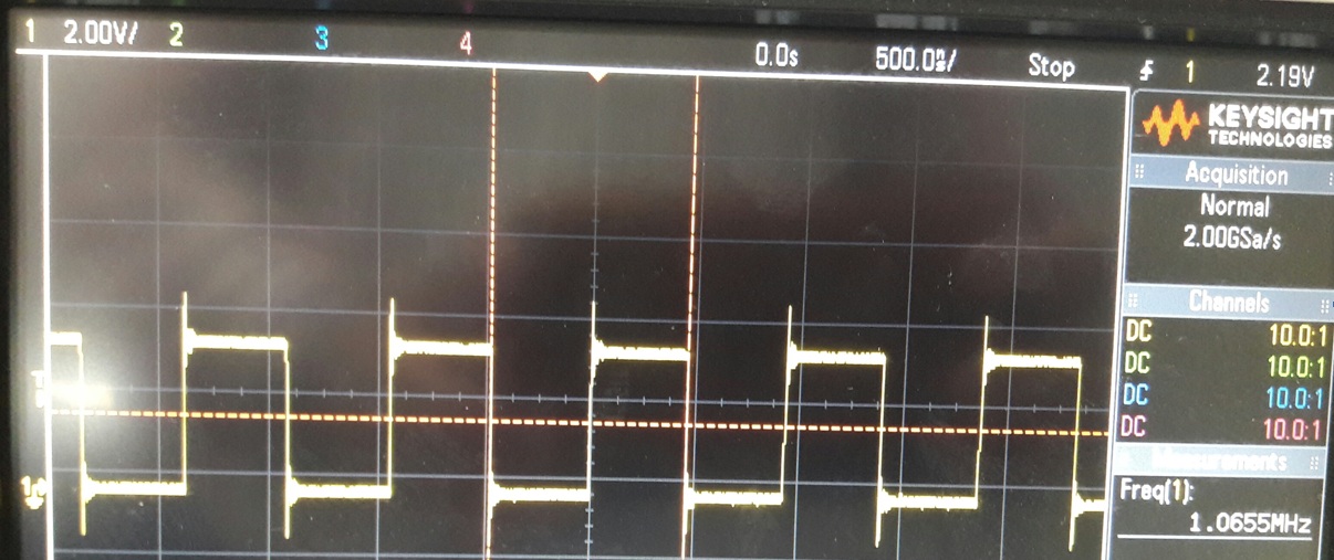
If i see at P7.7 using oscilloscope, it shows pulse of 1MHz instead of 4MHz. I am unable to find the solution.

But if I configure all three clock source with 32.768KHz, then all these three pins (P7.7, P1.0 & P2.2) have perfect 32.768 KHz signal.

All test are done using MSP430F5529 development board.

Regards,

Rajesh M.

  • UCSCTL5 |= DIVS_0;
    UCSCTL5 |= DIVPA_0 + DIVA_0;
    UCSCTL5 = DIVM_0;
    and check values of: DIVS_0, DIVPA_0 + DIVA_0, DIVM_0.
  • No XT2 faults?
    If XT2 not stable yet, DCOCLKDIV would be selected.

    It is my understanding.
    I would check it later.

  • Hello Rajesh,

    Please see the following code example for how to source XT2 to MCLK or SMCLK and output said clock. See example MSP430F55xx_UCS_08.c .

    dev.ti.com/.../
  •   // Loop until XT1,XT2 & DCO stabilizes - in this case loop until XT2 settles
      do
      {
        UCSCTL7 &= ~(XT2OFFG + XT1LFOFFG + DCOFFG);
                                                // Clear XT2,XT1,DCO fault flags
        SFRIFG1 &= ~OFIFG;                      // Clear fault flags
      }while (SFRIFG1&OFIFG);                   // Test oscillator fault flag

    You have the answer!
    Of course you need to wait until XT1 is stable, too!

  • Jace,
    I have a lack of registers programming level knowledge.
    I had some other duties and I had no time to check the issue at driverlib level.

    No doubts, Rajesh knows how to deal with it.
    Thanks!
    Fixed!
  • Hi Jace,

    I have copied your suggested code example as it is and checked the output frequency at P7.7. But the result is same with 1MHz. I have again checked with same arrangement after about 30 minutes, the frequency is same at 1MHz.

    ------------------------------------------------------------------------------------------------------------------------------------------------------------------------

    #include <msp430.h>

    int main(void)

    {

     WDTCTL = WDTPW + WDTHOLD;                 // Stop watchdog timer

     P2DIR |= BIT2;                            // SMCLK set out to pins

     P2SEL |= BIT2;                            

     P7DIR |= BIT7;                            // MCLK set out to pins

     P7SEL |= BIT7;

     P5SEL |= BIT2+BIT3;                       // Port select XT2

     UCSCTL6 &= ~XT2OFF;                       // Enable XT2

     UCSCTL3 |= SELREF_2;                      // FLLref = REFO

                                               // Since LFXT1 is not used,

                                               // sourcing FLL with LFXT1 can cause

                                               // XT1OFFG flag to set

     UCSCTL4 |= SELA_2;                        // ACLK=REFO,SMCLK=DCO,MCLK=DCO

     // Loop until XT1,XT2 & DCO stabilizes - in this case loop until XT2 settles

     do

     {

       UCSCTL7 &= ~(XT2OFFG + XT1LFOFFG + DCOFFG);

                                               // Clear XT2,XT1,DCO fault flags

       SFRIFG1 &= ~OFIFG;                      // Clear fault flags

     }while (SFRIFG1&OFIFG);                   // Test oscillator fault flag

     UCSCTL6 &= ~XT2DRIVE0;                    // Decrease XT2 Drive according to

                                               // expected frequency

     UCSCTL4 |= SELS_5 + SELM_5;               // SMCLK=MCLK=XT2

     while(1);                                 // Loop in place

    }

    ---------------------------------------------------------------------------------------------------------------------------------------------------------------------------

    Regards,

    Rajesh Maurya

  • XT2 drive decrease should be done according to a crystal specification.
    Could you comment out the decrease XT2 drive statement?
    Please check XT2 flags when measuring P7.7 frequency.
  • Hi Jash,
    With your example code I am able to get 4MHz frequency out. Actually today I have missed to set debugger mode because of this the old code was running.

    Thanks for your support. Now i will implement the required changes in my project file.

    Regards,
    Rajesh Maurya

**Attention** This is a public forum