This thread has been locked.

If you have a related question, please click the "Ask a related question" button in the top right corner. The newly created question will be automatically linked to this question.

MSP430FR2433: PCB is programmable but user code not starting

Part Number: MSP430FR2433
Other Parts Discussed in Thread: ENERGIA, MSP-EXP430FR2433,

Hi,

using the MSP-EXP430FR2433 Dev kit and Energia I can upload and run sketches successfully (i.e. the standard Blink example).

Now I made an own PCB with MSP430FR2433 based on this schematic (see attached):
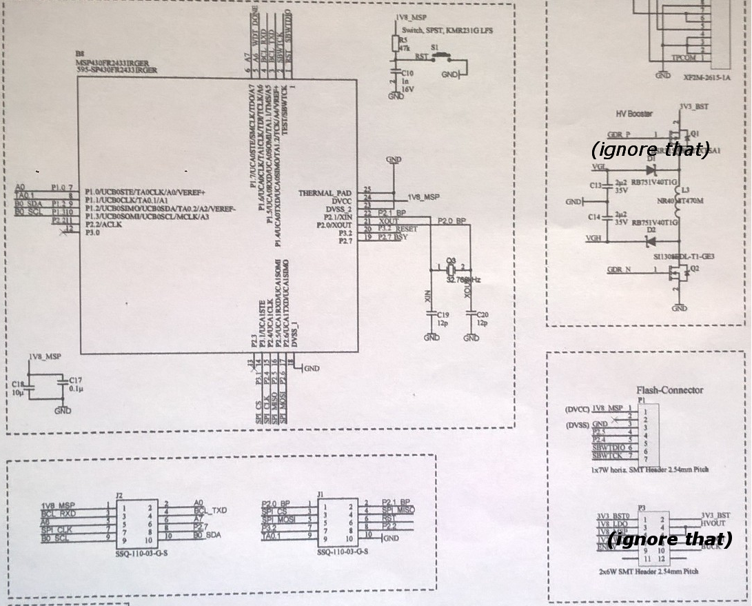
Connecting the new PCB with the jumper row of the Launchpad programmer, I can now upload the same blink example successfully to the new PCB.

However the user code does not seem to start since I cannot measure the switching voltage at the GPIO nor read back serial debugging messages.

Any help/ideas would be great.

Thanks,

Robert

  • Hi Robert,

    What do you mean you cannot measure the switching voltage of the GPIO nor read back serial debbuging messages? You use ADC to measure the voltage and UART to send debugging messages? Does the blink example work?

    B.R
    Winter
  • Hi,

    the user code is now running; using the blink sketch with a multimeter I can measure the switching voltage level at the defined GPIO (previously I was trying to use another GPIO with a connected external crystal).

    The serial.print() function over UART now also working fine after connecting the correct pins P1_4 and P1_5 (previously I was using P2_5 and P2_6).

    This solved my issue; we can close this topic.
    ;-)

    Thanks,
    Robert

**Attention** This is a public forum