


Tool/software: Code Composer Studio
hi,
ive been trying to configure spi of msp432p401r as master in 4 wire or 4 pin mode and use B1 instead of B0 based on the 3 wire master example provided. but i couldnt, i just want to transfer a data to slave using 4 wire mode the code i edited is given below please help me out. i get error in line 68 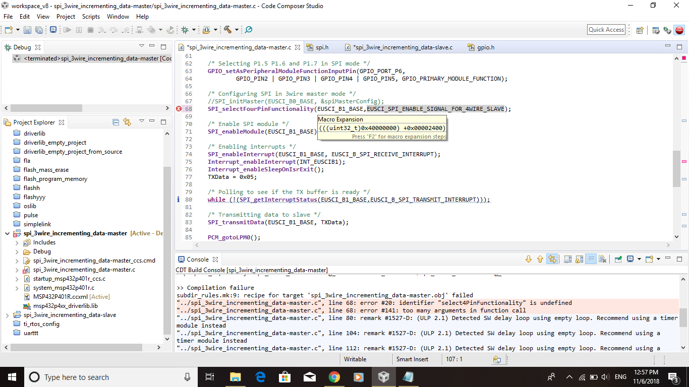
/* MSP432 SPI - 3-wire Master Incremented Data
 *
 * This example shows how SPI master talks to SPI slave using 3-wire mode.
 * Incrementing data is sent by the master starting at 0x01. Received data is
 * expected to be same as the previous transmission.  eUSCI RX ISR is used to
 * handle communication with the CPU, normally in LPM0. Because all execution
 * after LPM0 is in ISRs, initialization waits for DCO to stabilize against
 * ACLK.
 *
 * Note that in this example, EUSCIB0 is used for the SPI port. If the user
 * wants to use EUSCIA for SPI operation, they are able to with the same APIs
 * with the EUSCI_AX parameters.
 *
 * ACLK = ~32.768kHz, MCLK = SMCLK = DCO 3MHz
 *
 * Use with SPI Slave Data Echo code example.
 *
 *                MSP432P401
 *              -----------------
 *             |                 |
 *             |                 |
 *             |                 |
 *             |             P1.6|-> Data Out (UCB0SIMO)
 *             |                 |
 *             |             P1.7|<- Data In (UCB0SOMI)
 *             |                 |
 *             |             P1.5|-> Serial Clock Out (UCB0CLK)
 * Author: Timothy Logan
*******************************************************************************/
/* DriverLib Includes */
#include "driverlib.h"

/* Standard Includes */
#include <stdint.h>

#include <stdbool.h>

/* Statics */
static volatile uint8_t RXData = 0;
static uint8_t TXData = 0;

/* SPI Master Configuration Parameter */
const eUSCI_SPI_MasterConfig spiMasterConfig =
{
        EUSCI_B_SPI_CLOCKSOURCE_SMCLK,             // SMCLK Clock Source
        3000000,                                   // SMCLK = DCO = 3MHZ
        500000,                                    // SPICLK = 500khz
        EUSCI_B_SPI_MSB_FIRST,                     // MSB First
        EUSCI_B_SPI_PHASE_DATA_CHANGED_ONFIRST_CAPTURED_ON_NEXT,    // Phase
        EUSCI_B_SPI_CLOCKPOLARITY_INACTIVITY_HIGH, // High polarity
        EUSCI_SPI_4PIN_UCxSTE_ACTIVE_HIGH                       // 3Wire SPI Mode
};

int main(void)
{
    volatile uint32_t ii;

    /* Halting WDT  */
    WDT_A_holdTimer();

    /* Selecting P1.5 P1.6 and P1.7 in SPI mode */
    GPIO_setAsPeripheralModuleFunctionInputPin(GPIO_PORT_P6,
            GPIO_PIN2 | GPIO_PIN3 | GPIO_PIN4 | GPIO_PIN5, GPIO_PRIMARY_MODULE_FUNCTION);

    /* Configuring SPI in 3wire master mode */
    //SPI_initMaster(EUSCI_B0_BASE, &spiMasterConfig);
    SPI_selectFourPinFunctionality(EUSCI_B1_BASE,EUSCI_SPI_ENABLE_SIGNAL_FOR_4WIRE_SLAVE);

    /* Enable SPI module */
    SPI_enableModule(EUSCI_B1_BASE);

    /* Enabling interrupts */
    SPI_enableInterrupt(EUSCI_B1_BASE, EUSCI_B_SPI_RECEIVE_INTERRUPT);
    Interrupt_enableInterrupt(INT_EUSCIB1);
    Interrupt_enableSleepOnIsrExit();
    TXData = 0x05;

    /* Polling to see if the TX buffer is ready */
    while (!(SPI_getInterruptStatus(EUSCI_B1_BASE,EUSCI_B_SPI_TRANSMIT_INTERRUPT)));

    /* Transmitting data to slave */
    SPI_transmitData(EUSCI_B1_BASE, TXData);

    PCM_gotoLPM0();
    __no_operation();
}

//******************************************************************************
//
//This is the EUSCI_B0 interrupt vector service routine.
//
//******************************************************************************
void EUSCIB1_IRQHandler(void)
{
    uint32_t status = SPI_getEnabledInterruptStatus(EUSCI_B1_BASE);
    uint32_t jj;

    SPI_clearInterruptFlag(EUSCI_B1_BASE, status);

    if(status & EUSCI_B_SPI_RECEIVE_INTERRUPT)
    {
        /* USCI_B0 TX buffer ready? */
        while (!(SPI_getInterruptStatus(EUSCI_B1_BASE, EUSCI_B_SPI_TRANSMIT_INTERRUPT)));

        RXData = SPI_receiveData(EUSCI_B1_BASE);

        /* Send the next data packet */
        SPI_transmitData(EUSCI_B1_BASE, TXData);

        /* Delay between transmissions for slave to process information */
        for(jj=50;jj<50;jj++);
    }

}

