Hi,
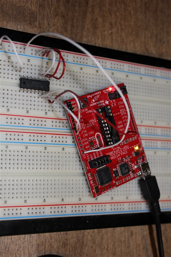
I have a TI PCF8574 I/O expander (http://search.digikey.com/scripts/DkSearch/dksus.dll?Detail&name=296-13109-5-ND) connected to MSP430 Launchpad (MSP430G2231) and having trouble in I2C communication with the expander using the attached code (not mine, used from some example).
Wiring:
SCL = P1.6
SDA = P1.7
A0, A1, A2 = GND
VCC = VCC

I/O expander I2C address is 0x20 (100000b) -> thus 0x40 is written to I2C bus to enable write mode (R/W is low)
The IO expander seems to ACK the address byte but there is a NACK (bolded line in I2C_State 8) for data byte and all pins remain HIGH.
What I would like to do is to set P0 to output/HIGH and all the other pins to output/LOW.
What am I doing wrong?
char MST_Data = 0x01; // Variable for transmitted data
char SLV_Addr = 0x40;
int I2C_State = 0; // State variable
void initialize(void)
{
WDTCTL = WDTPW + WDTHOLD; // Stop watchdog
if (CALBC1_1MHZ ==0xFF || CALDCO_1MHZ == 0xFF)
{
while(1); // If calibration constants erased
// do not load, trap CPU!!
}
BCSCTL1 = CALBC1_1MHZ; // Set DCO
DCOCTL = CALDCO_1MHZ;
P1OUT = 0xC0; // P1.6 & P1.7 Pullups, others to 0
P1REN |= 0xC0; // P1.6 & P1.7 Pullups
P1DIR = 0xFF; // Unused pins as outputs
USICTL0 = USIPE6+USIPE7+USIMST+USISWRST; // Port & USI mode setup
USICTL1 = USII2C+USIIE; // Enable I2C mode & USI interrupt
USICKCTL = USIDIV_3+USISSEL_2+USICKPL;
USICNT |= USIIFGCC; // Disable automatic clear control
USICTL0 &= ~USISWRST; // Enable USI
USICTL1 &= ~USIIFG; // Clear pending flag
_EINT();
}
void main(void)
{
initialize();
while(1)
{
USICTL1 |= USIIFG; // Set flag and start communication
// LPM0; // CPU off, await USI interrupt
// _NOP(); // Used for IAR
// for (i = 0; i < 5000; i++); // Dummy delay between communication cycles
}
}
/******************************************************
// USI interrupt service routine
******************************************************/
#pragma vector = USI_VECTOR
__interrupt void USI_TXRX (void)
{
switch(I2C_State)
{
case 0: // Generate Start Condition & send address to slave
// P1OUT |= 0x01; // LED on: sequence start
USISRL = 0x00; // Generate Start Condition...
USICTL0 |= USIGE+USIOE;
USICTL0 &= ~USIGE;
USISRL = SLV_Addr; // ... and transmit address, R/W = 0
USICNT = (USICNT & 0xE0) + 0x08; // Bit counter = 8, TX Address
I2C_State = 2; // Go to next state: receive address (N)Ack
break;
case 2: // Receive Address Ack/Nack bit
USICTL0 &= ~USIOE; // SDA = input
USICNT |= 0x01; // Bit counter = 1, receive (N)Ack bit
I2C_State = 4; // Go to next state: check (N)Ack
break;
case 4: // Process Address Ack/Nack & handle data TX
USICTL0 |= USIOE; // SDA = output
if (USISRL & 0x01) // If Nack received...
{ // Send stop...
USISRL = 0x00;
USICNT |= 0x01; // Bit counter = 1, SCL high, SDA low
I2C_State = 10; // Go to next state: generate Stop
P1OUT |= 0x01; // Turn on LED: error
}
else
{ // Ack received, TX data to slave...
USISRL = MST_Data; // Load data byte
USICNT |= 0x08; // Bit counter = 8, start TX
I2C_State = 6; // Go to next state: receive data (N)Ack
// P1OUT &= ~0x01; // Turn off LED
}
break;
case 6: // Receive Data Ack/Nack bit
USICTL0 &= ~USIOE; // SDA = input
USICNT |= 0x01; // Bit counter = 1, receive (N)Ack bit
I2C_State = 8; // Go to next state: check (N)Ack
break;
case 8: // Process Data Ack/Nack & send Stop
USICTL0 |= USIOE;
if (USISRL & 0x01) // If Nack received...
{
P1OUT |= 0x01; // Turn on LED: error
}
else // Ack received
{
P1OUT &= ~0x01; // Turn off LED
}
// Send stop...
USISRL = 0x00;
USICNT |= 0x01; // Bit counter = 1, SCL high, SDA low
I2C_State = 10; // Go to next state: generate Stop
break;
case 10:// Generate Stop Condition
USISRL = 0x0FF; // USISRL = 1 to release SDA
USICTL0 |= USIGE; // Transparent latch enabled
USICTL0 &= ~(USIGE+USIOE);// Latch/SDA output disabled
I2C_State = 0; // Reset state machine for next transmission
// LPM0_EXIT; // Exit active for next transfer
break;
}
USICTL1 &= ~USIIFG; // Clear pending flag
}

