This thread has been locked.

If you have a related question, please click the "Ask a related question" button in the top right corner. The newly created question will be automatically linked to this question.

MSP430FR2633: UART and I2C on Same 8MHz Clock issue

Part Number: MSP430FR2633
Other Parts Discussed in Thread: ADS122C04

I want to interface two external peripherals on same MSP430FR2633 Micro controller.

One device is on UART and another one is on I2C.

Firstly, I have configured my UART on 8 MHz clock with 9600 baud rate and my UART device working up to date properly on same frequency with baud rate.
The problem with my code is I2C device not responding on same frequency with define prescaler value.

My I2C code is working with 1MHz clock. And I want to run my I2C on 8MHz clock (SMCLK).

So, how can I run on same MSP430FR2633 with this I2C interface on same 8MHz clock.

Please do needful.

Here is my code:

#include <msp430fr2633.h>


int main(void)
{
    WDTCTL = WDTPW | WDTHOLD;               // Stop watchdog timer
    PM5CTL0 &= ~LOCKLPM5;

 
    //8MHz Clock Configuration
    __bis_SR_register(SCG0);                 // disable FLL
    CSCTL3 |= SELREF__REFOCLK;               // Set REFO as FLL reference source
    CSCTL0 = 0;                              // clear DCO and MOD registers
    CSCTL1 &= ~(DCORSEL_7);                  // Clear DCO frequency select bits first
    CSCTL1 |= DCORSEL_3;                     // Set DCO = 8MHz
    CSCTL2 = FLLD_0 + 243;                   // DCODIV = 8MHz
    __delay_cycles(3);
    __bic_SR_register(SCG0);                 // enable FLL
    while(CSCTL7 & (FLLUNLOCK0 | FLLUNLOCK1)); // Poll until FLL is locked

    CSCTL4 = SELMS__DCOCLKDIV | SELA__REFOCLK; // set default REFO(~32768Hz) as ACLK source, ACLK = 32768Hz
                                             // default DCODIV as MCLK and SMCLK source

    // Configure Pins for I2C
    P1SEL0 |= BIT2 | BIT3;                  // I2C pins
    //I2C Configuration for 1 MHz clock
    UCB0CTLW0 |= UCSWRST;                   // put eUSCI_B in reset state
    UCB0CTLW0 |= UCMODE_3 | UCMST | UCSYNC; // I2C master mode, SMCLK, USC SYNC Mode
    UCB0BRW = 0x8;                          // Set Bit rate 100 kHz
    UCB0I2CSA = 0x40;                       // ADC122C04 slave Device address
    UCB0CTLW0 &= ~UCSWRST;                  // Software Reset Disable
    UCB0IE |= UCTXIE0 | UCNACKIE;           // Tx Interrupt Enable, Not-acknowlege Interrupt Enable for if Negative Ack then Repeat Start


    // Configure UART0 
    P1SEL0 |= BIT4 | BIT5;                          // Set P1.4 and P1.5 as UART0 Mod
    UCA0CTLW0 |= UCSWRST;                           // Software Reset Enable
    UCA0CTLW0 |= UCSSEL_3;                     // Set ACLK as BRCLK
    UCA0BR0 = 52;                                   // 8000000/16/9600
    UCA0BR1 = 0x00;
    UCA0MCTLW = 0x4900 | UCOS16 | UCBRF_10;          // 9600 Baud Rate Setting from the User Guide Table

}

  • > UCB0BRW = 0x8; // Set Bit rate 100 kHz
    8MHz/8=1MHz, not 100kHz. Try:
    > UCB0BRW = 80; // Set Bit rate 8MHz/80-=100 kHz
  • Hi Bruce,

    I have a tried with UCB0BRW = 80 in I2C Configuration.
    But my I2C device is not responding.

    Regards,
    Kelvin
  • Hi Kevin,

    Bruce is right with the divider settings but you also need to select SMCLK as clock source.
    So the code line needs to look like this:
    UCB0CTLW0 |= UCSSEL_3 | UCMODE_3 | UCMST | UCSYNC; // I2C master mode, SMCLK, USC SYNC Mode

    (I am not sure how this code could work on 1MHz without the selection.)

    Regards,
    Stefan
  • Hi Stefan,

    I have a change my code according to your suggestion and also configure UCB0BRW = 80. 

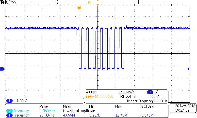
    But, it gives me 98.03KHz on oscilloscope.

    I have a also attached screenshot of oscilloscope of SCL Line

    Still, I'm not getting any respond from the my I2C Device.

    Please do needful.


  • 9 clock pulses, then nothing, looks rather like a NACK. If you can get SDA on the second channel that would help.

    How are the A0/A1 pins set? Also, where is your actual I2C transaction code?

    > (I am not sure how this code could work on 1MHz without the selection.)
    (UCSSEL_3 is pre-selected at reset.)
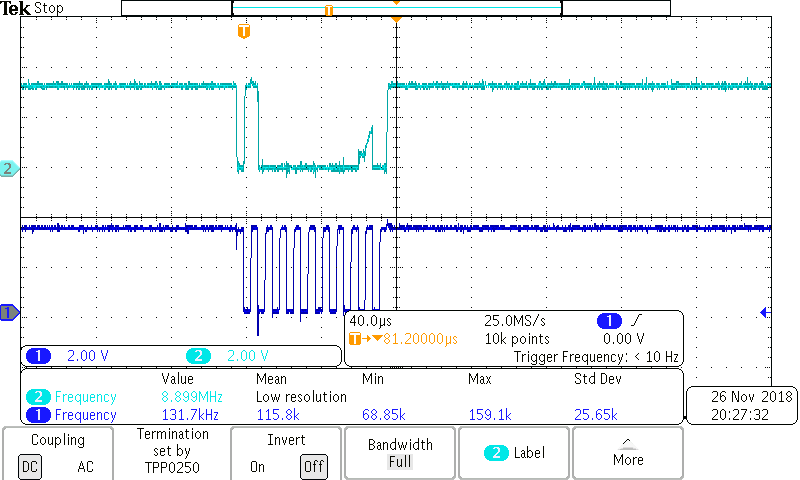
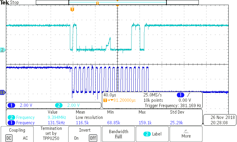
  • Please find attached files

    For 8 MHz frequency 

    and


    Working with 1MHz 

    Thanks in advance

  • Hi Kelvin,

    Interresting pictures:
    The timing looks already OK, so the clock divider settings are good.

    1Mhz send two characters and goes then into clock stretching where most properly the slave hold the clock low and will then stuck there. So for me that also looks wrong.
    8 Mhz just send one byte but everything looks OK till then.

    Can you share your code again. The one 8n the first mail just did contain the init part.

    Regards,
    Stefan
  • Hi Stefan,

    I'm using ADS1220C04 Ti's ADC as a I2C Device.

    Here is my Code:

    Please go through it and do needful.

    #include <msp430fr2633.h>
    
    unsigned int Count = 0;
    int Start_Loop = 0, RECEIVED_Data = 0;      // Variable Declaration
    
    
    void I2C_Send_Reset_Command();                  // Function to Reset the slave device
    
    
    unsigned int I2C_Tx_Counter = 0;                // Tx Counter Declaration
    unsigned int I2C_Rx_Counter = 0;                // Rx Counter Declaration
    unsigned int I2C_Tx_Int_Counter = 0;
    unsigned int I2C_Rx_Int_Counter = 0;
    unsigned int I2C_Tx_Data[9];                     // Array for Tranmitting the command to slave device
    int I2C_Rx_Data[3];                             // Array for Receving byte from slave device
    void 8MHz_clock();
    
    int main(void)
    {
        WDTCTL = WDTPW | WDTHOLD;               // Stop watchdog timer
    
        // Configure GPIO
        P2DIR &= ~BIT2;                         // Set P1.0 to output direction
    
        //P1OUT &= ~BIT2;                       // Configure P1.3 as pulled-up
        P2REN &= ~BIT2;                         // P1.3 pull-up register enable
        P2IES |= BIT2;                          // P1.3 High/Low edge
        P2IE |= BIT2;                           // P1.3 interrupt enabled
    
        PM5CTL0 &= ~LOCKLPM5;
    
                     // SMCLK, UP mode
        8MHz_clock();
        // Configure Pins for I2C
        P1SEL0 |= BIT2 | BIT3;                  // I2C pins


        I2C_Send_Reset_Command();                   // Reset Command
        while (UCB0CTLW0 & UCTXSTP);            // Ensure stop condition got sent
    
    
        while(1)
        {
            __bis_SR_register(GIE);             // Global Interrupt Enable
            __no_operation();                   // For debugging Set Break Point here
        }
    }
    
    /////////////////////////////////////////////////////////////////////
    ////                                                            /////
    ////                    I2C Reset Command                       /////
    ////                                                            /////
    /////////////////////////////////////////////////////////////////////
    void I2C_Send_Reset_Command()
    {
        UCB0CTLW0 |= UCSWRST;                   // put eUSCI_B in reset state
        UCB0CTLW0 |= UCMODE_3 | UCMST | UCSYNC; // I2C master mode, SMCLK, USC SYNC Mode
        UCB0BRW = 0x3B;                          // Set Bit rate 100 kHz
        UCB0I2CSA = 0x40;                       // ADC122C04 slave Device address
        UCB0CTLW0 &= ~UCSWRST;                  // Software Reset Disable
    
        I2C_Tx_Counter = 1;                         // Set Transmit data counter value
        I2C_Tx_Data[1] = 0x06;                       // Reset Command = 0x06
    
        while (UCB0CTLW0 & UCTXSTP);            // Ensure stop condition got sent
        UCB0CTLW0 |= UCTR | UCTXSTT;            // I2C TX, start condition
        UCB0IE |= UCTXIE0 | UCNACKIE;           // Tx Interrupt Enable, Not-acknowlege Interrupt Enable for if Negative Ack then Repeat Start
    
        __bis_SR_register(GIE);                 // Global Interrupt Enable
    
        while(I2C_Tx_Counter > 0)                   // Wait for Reset Command Set
        {
            __no_operation();
        }
    
        __delay_cycles(500);                    // Wait to settle power up
        _no_operation();                        // For debugging Set Break Point here
    }
    
    void 8MHz_clock()
    {
        __bis_SR_register(SCG0);                 // disable FLL
            CSCTL3 |= SELREF__REFOCLK;               // Set REFO as FLL reference source
            CSCTL0 = 0;                              // clear DCO and MOD registers
            CSCTL1 &= ~(DCORSEL_7);                  // Clear DCO frequency select bits first
            CSCTL1 |= DCORSEL_3;                     // Set DCO = 8MHz
            CSCTL2 = FLLD_0 + 243;                   // DCODIV = 8MHz
            __delay_cycles(3);
            __bic_SR_register(SCG0);                 // enable FLL
            while(CSCTL7 & (FLLUNLOCK0 | FLLUNLOCK1)); // Poll until FLL is locked
    
            CSCTL4 = SELMS__DCOCLKDIV | SELA__REFOCLK; // set default REFO(~32768Hz) as ACLK source, ACLK = 32768Hz
                                                     // default DCODIV as MCLK and SMCLK source
    
            //CSCTL5 |= DIVM_0 | DIVS_2;              // SMCLK = MCLK/4 = 2MHZ,
    }


    /////////////////////////////////////////////////////////////////////
    ////                                                            /////
    ////                    I2C ISR                                 /////
    ////                                                            /////
    /////////////////////////////////////////////////////////////////////
    #if defined(__TI_COMPILER_VERSION__) || defined(__IAR_SYSTEMS_ICC__)
    #pragma vector = USCI_B0_VECTOR
    __interrupt void USCIB0_ISR(void)
    #elif defined(__GNUC__)
    void __attribute__ ((interrupt(USCI_B0_VECTOR))) USCIB0_ISR (void)
    #else
    #error Compiler not supported!
    #endif
    {
      switch(__even_in_range(UCB0IV,USCI_I2C_UCBIT9IFG))
      {
            case USCI_NONE: break;              // Vector 0: No interrupts break;
            case USCI_I2C_UCALIFG: break;
            case USCI_I2C_UCNACKIFG:            // Resend start if NACK
                UCB0CTL1 |= UCTXSTT;            // Transmit STOP Condition in Master Mode
              break;                            // Vector 4: NACKIFG break;
            case USCI_I2C_UCSTTIFG: break;      // Vector 6: STTIFG break;
            case USCI_I2C_UCSTPIFG: break;      // Vector 8: STPIFG break;
            case USCI_I2C_UCRXIFG3: break;      // Vector 10: RXIFG3 break;
            case USCI_I2C_UCTXIFG3: break;      // Vector 14: TXIFG3 break;
            case USCI_I2C_UCRXIFG2: break;      // Vector 16: RXIFG2 break;
            case USCI_I2C_UCTXIFG2: break;      // Vector 18: TXIFG2 break;
            case USCI_I2C_UCRXIFG1:  break;     // Vector 20: RXIFG1 break;
            case USCI_I2C_UCTXIFG1: break;      // Vector 22: TXIFG1 break;
            case USCI_I2C_UCRXIFG0:             // Vector 24: RXIFG0 break;
                RECEIVED_Data = UCB0RXBUF;
                I2C_Rx_Data[I2C_Rx_Counter] = UCB0RXBUF;// Load RxBuffer data to ADC_ADC_Rx_Data
                I2C_Rx_Counter++;                   // Increment Rx Counter
                I2C_Rx_Int_Counter++;
                if(I2C_Rx_Counter == 3)             // wait untill 3 byte receive
                {
                    UCB0CTLW0 |= UCTXSTP;       // I2C Stop Condition
                    UCB0IE  &= ~UCRXIE0;        // I2C Rx Interrupt Disable
                    UCB0IFG &= ~UCRXIFG0;       // Clear Rx interrupt Flag
                    break;
                }
                break;
            case USCI_I2C_UCTXIFG0:             // Vector 26: TXIFG0 break;
                UCB0TXBUF = I2C_Tx_Data[I2C_Tx_Counter]; // load Data to Tx Buffer
                I2C_Tx_Counter--;                   // Decrement Tx Counter
                I2C_Tx_Int_Counter++;
                if(I2C_Tx_Counter == 0)             // wait untill Tx counter set 0
                {
    
                    UCB0IE &= ~UCNACKIE;        // Not - Acknowledge  Interrupt Disable
                    UCB0CTLW0 |= UCTXSTP;       // I2C Stop Condition
                    UCB0IFG &= ~UCTXIFG0;       // I2C disable interrupt flag
                    UCB0IE  &= ~UCTXIE0;        // Diable Tx Interrupt flag
                }
                break;
            case USCI_I2C_UCBCNTIFG:break;      // Vector 28: BCNTIFG
            case USCI_I2C_UCCLTOIFG:break;      // Vector 30: clock low timeout
            case USCI_I2C_UCBIT9IFG:break;      // Vector 32: 9th bit
            default: break;
      }
    }
    
    /////////////////////////////////////////////////////////////////////
    ////                                                            /////
    ////                    Port 2 ISR                              /////
    ////                                                            /////
    /////////////////////////////////////////////////////////////////////
    #if defined(__TI_COMPILER_VERSION__) || defined(__IAR_SYSTEMS_ICC__)
    #pragma vector=PORT2_VECTOR
    __interrupt void Port_2(void)
    #elif defined(__GNUC__)
    void __attribute__ ((interrupt(PORT1_VECTOR))) Port_2 (void)
    #else
    #error Compiler not supported!
    #endif
    {
    
        P2IFG &= ~BIT2;                         // Clear P1.2 IFG
        Count = Count + 1;                      // To Check How Many times this ISR Call
       // I2C_Read_ADS2210();                         // Read Function call
    }

    Regards,

    Kelvin

  • Hi Kevin,

    from your code i think there are two think you need to change:

            case USCI_I2C_UCNACKIFG:            // Resend start if NACK
                UCB0CTL1 |= UCTXSTT;            // Transmit STOP Condition in Master Mode
              break;                            // Vector 4: NACKIFG break;


            case USCI_I2C_UCTXIFG0:             // Vector 26: TXIFG0 break;
                if(I2C_Tx_Counter == 0)             // wait untill Tx counter set 0
                {
    
                    UCB0IE &= ~UCNACKIE;        // Not - Acknowledge  Interrupt Disable
                    UCB0CTLW0 |= UCTXSTP;       // I2C Stop Condition
                    UCB0IFG &= ~UCTXIFG0;       // I2C disable interrupt flag
                    UCB0IE  &= ~UCTXIE0;        // Diable Tx Interrupt flag
                }else{
                    UCB0TXBUF = I2C_Tx_Data[I2C_Tx_Counter]; // load Data to Tx Buffer
                    I2C_Tx_Counter--;                   // Decrement Tx Counter
                    I2C_Tx_Int_Counter++;
                }
                break;
    

    Note: as i do not have the setup i could not test this.

    1. On a case of NACK you should send STOP not START

    2. From you scope shots: with 8MHz it sends the STOP right after the address. So you do send the STOP to early. When putting the first and last byte into the TX Buffer it is still in the buffer when you set the stop bit when running with 8MHz. On 1MHz this may already be in the transmit state so it will put the STOP out on the bus after the data.

    Regards,

     Stefan

  • Hi Steafn,

    I have a implemented the changes that was suggested by you.

    first changes not working in my code and controller get stuck.

    second changes worked.

    Here I'm sharing more detail about my problem.

    I'm Interfacing ADS122C04 (ADC 24 - Bit) with MSP430FR2633 using I2C on 8 MHz Clock SMCLK Clock.

    I'm using 10k resistor value as a pull-up and have a selected 100 kbps speed for I2C from the 8MHz SMCLK Clock.

    The Pin connection I did from below figure.

    I'm trying to interface ADS122C04 24-bit ADC with MSP430FR2633

    I have written following algorithm:

    1. Send Reset Command (0x06)

    2. Write Configuration Register

    a. Register 0 (0x40) = 0x81;

    b. Register 1 (0x44) = 0x04;

    c. Register 2 (0x48) = 0x00;

    d. Register 3 (0x4C) = 0x00;

    //Here I'm using Single short conversation mode and Single channel Read Mode

    3. Send Start Command (0x08);

    4.loop

    {

    Wait for DRDY Pin to transition low;

    send Read Command (0x10);

    }

    The DRDY pin goes low after sending the start command.

    The Above algorithm I have a implemented and I'm able to read only data = [0xFF, 0xFF, 0xFF] from ADC every time.
    I'm also giving different voltage using potentio-meter on AIN0 Channel from 0 to 3.3v but I receive same data  (data = [0xFF, 0xFF, 0xFF]) on different voltages

    Here is my 8MHz Clock Configuration:
    {
        __bis_SR_register(SCG0);                 // disable FLL
        CSCTL3 |= SELREF__REFOCLK;               // Set REFO as FLL reference source
        CSCTL0 = 0;                              // clear DCO and MOD registers
        CSCTL1 &= ~(DCORSEL_7);                  // Clear DCO frequency select bits first
        CSCTL1 |= DCORSEL_3;                     // Set DCO = 8MHz
        CSCTL2 = FLLD_0 + 243;                   // DCODIV = 8MHz
        __delay_cycles(3);
        __bic_SR_register(SCG0);                 // enable FLL
        while(CSCTL7 & (FLLUNLOCK0 | FLLUNLOCK1)); // Poll until FLL is locked
    
        CSCTL4 = SELMS__DCOCLKDIV | SELA__REFOCLK; // set default REFO(~32768Hz) as ACLK source, ACLK = 32768Hz
                                                         // default DCODIV as MCLK and SMCLK source
    }
    
    Here is my I2C Configuration:
    {
        UCB0CTLW0 |= UCSWRST;                   // Put eUSCI_B in reset state
        UCB0CTLW0 |= UCMODE_3 | UCSSEL_3 | UCMST | UCSYNC; // I2C master mode, SMCLK
        UCB0BRW = 0x33;                          // Set Bit rate 100 kHz
        UCB0I2CSA = 0x40;                       // ADC122C04 slave Device address
        UCB0CTLW0 &= ~UCSWRST;                  // Software Reset Disable
    
    }

    Please do needful.

    Regards,

    Kelvin

  • Hi Kevin,

    get always a result of 0xFFFFFF looks like the reference is not correctly set or selected.

    Can you check that again. For me it looks like after a brief check that you have selected an external reference but the schematic shows no signal connection there.

    Regards,

     Stefan

  • Hi Stefan,

    I was forget to tell you that I used Avss pin as reference source. and I have a checked with this pin also probe it, gives me 3.3v

    Regards,
    Kelvin
  • Hi Kevin,

    i guess you meant AVCC = 3.3 V and AVSS = 0V.
    Can you do some check on I2C communication, e.g.
    - Readback of control registers
    - check another channel e.g. Temp sensor (Temperature sensor mode)

    Regards,
    Stefan
  • Hi Stefan,

    Thanks for your prompt reply and valuable suggestions.
    Already, I have attempt all the suggestions of yours. Also, verify what I have a written to register and read back using Register Read command.
    It seems to good. There is no error in this iteration.

    My code is working by little change in I2C configuration.
    Here is my I2C Configuration:
    {
    UCB0CTLW0 |= UCSWRST; // Put eUSCI_B in reset state
    UCB0CTLW0 |= UCMODE_3 | UCSSEL_3 | UCMST | UCSYNC; // I2C master mode, SMCLK
    UCB0BRW = 0x8; // Set Bit rate 100 kHz
    UCB0I2CSA = 0x40; // ADC122C04 slave Device address
    UCB0CTLW0 &= ~UCSWRST; // Software Reset Disable

    }

    I have a change UCB0BRW register setting only.
    Chnaged UCB0BRW = 0x33 to UCB0BRW = 0x8

    After changing this setting I also getting accurate counts on ANI0 Channels.

    Regards,
    Kelvin Kalariya

**Attention** This is a public forum