This thread has been locked.

If you have a related question, please click the "Ask a related question" button in the top right corner. The newly created question will be automatically linked to this question.

CCS/MSP430FR2422: can not move PWM signal from TA1.1 to TA0.1

Part Number: MSP430FR2422


Tool/software: Code Composer Studio

Hallo,

at the 20pin-version I have to move a PWM signal from TA1.1 to TA0.1 to get TA1 available for other purpose (ADC-triggering). Since both timers are of type A I do the same thing at all registers TA0xyz that I'd successfully done with TA1xyz before. The pin configuration, however is different:

TA1.1 used pin 13 with P2SELx=01b and P2DIR.x=1

TA0.1 shall use pin 17 with P2SELx=10b and P1Dir.x=1

Configuring UCA0TXD instead of TA0.1 for this pin also does not work. However, configuring P1.4-IO instead of TA0.1 for this pin works fine!!!

Reading the counter value TA0R shows that the counter is running. It is only the pin which seams to fail when configured for TA0.1.

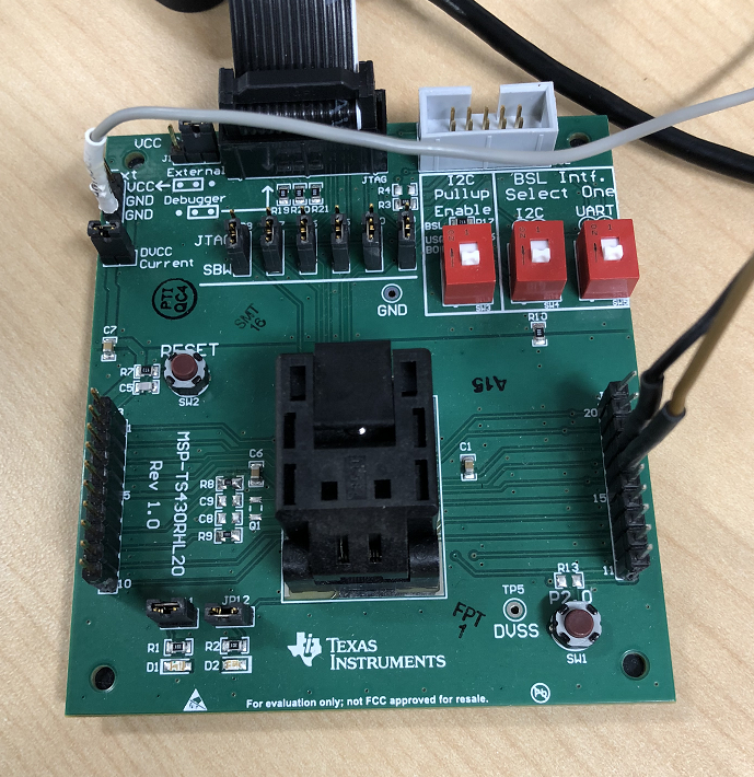
I use the evaluation board MSP-TS430-RHL20 with all jumpers (JP5 - JP10) set to SBW and SW3 - SW5 set to OFF. Flashing and debuggigs works well.

By the way TA0.1 at pin 16 as document SLASEE5A (data sheet) tells seams to be wrong, but pin 17 as document SLAU278AE (Hardware Tools User's Guide) tells seams to be correct. I conclude this since P1.4 works at pin 17. Anyway I checked both pins.

Is there any idea what else to consider to let the signal out of pin 17?

Best regards

Stefan

  • Hello Stefan,

    Thanks posting your question.
    We will look into this and get back to you ASAP.

    Thanks,
    Yiding
  • Hello Stefan,

    I have attached the example code to output the PWM on TA0.1 and TA0.2, this example program generates two PWM outputs on P1.4 (pin 17),P1.5 (pin 16) using Timer0_A configured for up mode. The value in CCR0, 1000-1, defines the PWM period and the values in CCR1 and CCR2 the PWM duty cycles. Using ~1MHz SMCLK as TACLK, the timer period is ~1ms with a 75% duty cycle on P1.4 and 25% on P1.5.

    ACLK = default REFO ~32768Hz, MCLK = SMCLK = default DCODIV ~1MHz

    msp430fr2422_ta0_16.c.zip

    And this is how I connected to the MSP-TS430-RHL20 board with the logic analyzer to monitor the PWM signal:

    And this is the output of the logic analyzer which shows 2 PWM signal with 75% and 25% duty cycle.

    Please let me know if you have any questions.

    Thanks,

    Yiding

  • Hello Yiding,

    sorry for the delay. Other very urgent projects got temporarily a higher priority.

    Yes, the support you gave to me resolved this issue. Thanks a lot.

    Best regards
    Stefan

**Attention** This is a public forum