This thread has been locked.

If you have a related question, please click the "Ask a related question" button in the top right corner. The newly created question will be automatically linked to this question.

MSP430FR2633: CapTIvate Design Center Usage Tips

Part Number: MSP430FR2633
Other Parts Discussed in Thread: CAPTIVATE-BSWP, CAPTIVATE-FR2633

I am working with the CAPTIVATE-BSWP module out of the box and my own thick (3/8") glass overlay. I am tuning the parameters in the CapTIvate Design Center (Conversion_Control and Tuning tabs for the keypadSensor) and trying to achieve "Good" margin values in the SNR measurement. I have come across a number of issues.

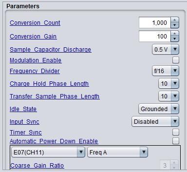
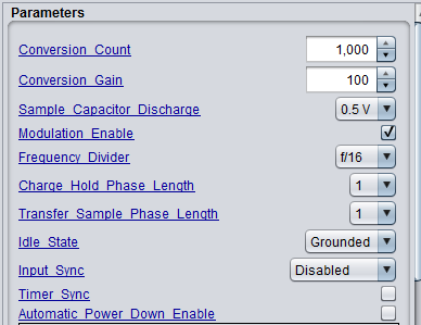
1. Some settings, particularly in Conversion_Control do not get set properly when I hit the Apply button. This is especially true for setting the Frequency Divider and Modulation Enable option. I will select my values and hit Apply, but when I Read them back out they are their old values and I cannot change them. Eventually the setting will stick after I go do something else and come back.

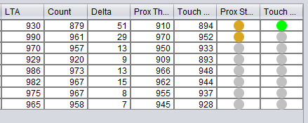
2. If I change the Conversion Count I can get the data display update rates to slow significantly. I can have things running well and the Channel Bar Chart and Channel Table are updating several times per second at, say, a Conversion Count of 1000. Then I raise the Conversion Count to 1250 and the displays update twice per second or slower and don't respond to touches or proximity on the keypadSensor. I can even change the Conversion Count back down to 1000 and the updates are still slow. I have to do some unknown (to me) sequence of changing parameters and/or resetting the MCU to get things running smoothly again. 

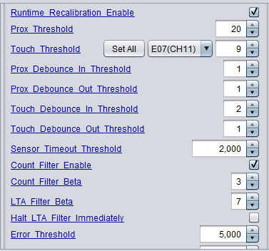
3. I constantly get the Max Count Error. Even when it is set to 5000 or 8191 I get the error but never see a bad reading on the data displays.

Do you have any advice for these issues?

  • Hello Nathan,

    Thanks for posting your question.
    You mentioned that you are using the CAPTIVATE-BSWP module out of box, do you by any chance modified the code on CAPTIVATE-FR2633 board?
    I will recommend first to re-program the CAPTIVATE-FR2633 board with the BSWP out of box demo program and it should be in C:\Users\yourusername\CapTIvateDesignCenter_1_70_00_03\CapTIvateDesignCenterWorkspace\CAPTIVATE-BSWP\demo_src

    Regarding your issues:
    1. Do you only see this on Frequency Divider and Modulation Enable options? Just want to confirm with you that for example, if you changed the Frequency Divider from f/4 to f/8 and you hit Apply and you hit Read and you see the Frequency Divider showing f/4 right?

    2. When you see this happen, what is your frequency divider setting?

    3. When you say you constantly getting the Max Count Error, do you mean that even after you hit Clear Flags and you are still keep getting the Max Count Error LED in the CapTIvate Design Center?

    We will help you to get these issues resolved and I just want to make sure we have the same configurations. I just tried the out of box configuration and did not experience the issues you are having.

    Thanks,
    Yiding
  • I have not modified the code at all.

    1. Yes, that is the behavior I sometimes see. I can't remember if I have seen it with the Conversion Count and Conversion Gain settings or if I changed those to try to get the other changes to stick.

    2. Today, f/16, but I think it has happened at other settings. This doesn't happen every time and I can't reliably make it happen.

    3. That's correct. The Max Count Error flag keeps being being asserted even after I clear it.

    Here are my parameters in case I've missed something.

  • Hello Nathan,

    Thanks for the detail explanation on your issues.

    Based on your configuration, I notice the Charge Hold Phase Length and Transfer Sample Phase Length are set to 10. Any reason why you want to set these two parameters to 10?

    For a typical design we recommend to keep these two parameters to default 1. 

    As the picture shows below, each measurement, or "conversion," consists of a series of charge transfers. For a self capacitance sensor, a charge transfer is composed of a charge phase and a transfer phase. When you set the Charge and Transfer Phase Length to 10 that means it takes 10 conversion clock (in your case, f/16) cycles to complete one charge transfer step. This means the scan time for all your sensors will be really long. For typical design and also for the BSWP board you are using, we recommend to use 1 for both charge phase and transfer phase length.  

    Please try this and let me know if you still have these issues.

    Thanks,

    Yiding

  • I had some success in getting better sensitivity through the thick glass overlay when I increased those parameters. Is that coincidence or is that expected behavior?
  • Hello Nathan,

    By changing the charge and transfer phase length you are essentially changing the conversion frequency. The purpose of a slower conversion frequency is to make sure the sensor electrode is being fully charged and fully transfered if the electrode has large capacitance. For the BSWP board keypad sensor, if the frequency divider is higher than f/4 (f/8, f/16 .....), you should only seen small sensitivity changes with the conversion frequency .

    For a normal button application, ~50 counts of delta should be enough and with your (3/8'') glass overlay, do you need to increase the conversion count to 1000 to be able to get 50 counts of delta?

    If the conversion time is too long, it takes long time to calibrate and I think that is why you were experiencing these strange communication issues. When you change the phase length back to 1, do you still have these issues?

    Thanks,
    Yiding

  • It seems to be running better with shorter phase lengths, but the only situation I've been able to get a "Good" evaluation in the SNR tool is with the phase lengths set at 10. If I keep the phase lengths low, can I increase the Conversion Count to compensate or am I missing the point?
  • Hello Nathan,

    What is the delta you are getting with 1000 conversion count and (3/8'') glass?

    Thanks,
    Yiding
  • Hello Nathan,

    I think "CHARACTERIZATION ADVISED" is ok for your initial evaluation on the BSWP board and with your glasses setup. Because the BSWP board has a 1.5mm overlay and also you don't have the good bounding between glasses and the BSWP board which means in your actual design the overlay thickness will be thinner without the 1.5mm polycarbonate and with better bounding and also you can design the sensor to be larger. All of these will increase your sensitivity from the hardware design perspective.

    Thanks,
    Yiding

**Attention** This is a public forum