This thread has been locked.

If you have a related question, please click the "Ask a related question" button in the top right corner. The newly created question will be automatically linked to this question.

MSP430FR4133: External Sensor MCP9808 interfaced with MSP430FR4133

Part Number: MSP430FR4133
Other Parts Discussed in Thread: MSP430WARE

Tool/software: IAR Embedded

 Hello,

 I'm a beginner on MSP430 and programming, and need some help with a project of mine.

Project- To interface an external temperature sensor MCP9808 through I2C communication with MSP430FR4133 to get temperature value.

Connections

SDA- pin 5.2

SCL- pin 5.3

GND-GND

VDD- 3.3V

I have interfaced a temperature sensor  MCP9808 with MSP430FR4133 trough i2c communication. I am using the following code to read the output voltage from the sensor. But it doesn't seem to be working. Could you please have a look?


#define I2C__MSP430FR4133_H_

#include <MSP430.h>
#include <stdint.h>
#include <stdio.h>

#define AMBIENT_TEMPERATURE 0x05
#define DEVICE_ID_REGISTER 0x04
#define MANUFACTURE_ID_REGISTER 0x0054

uint16_t tlen =7;
uint16_t rlen =7;
int *tx =NULL;
int *rx =NULL;
uint8_t addr = 0x18;


volatile unsigned char RXData;

long temp;
void Stop_WD (void);
void Set_I2C(void);


uint16_t I2C_write(void* tx, uint16_t tlen,uint8_t addr);
uint16_t I2C_read(void* rx, uint16_t rlen, uint8_t addr);


int main(void)
{
Stop_WD();

// Disable the GPIO power-on default high-impedance mode to activate
// previously configured port settings
PM5CTL0 &= ~LOCKLPM5;

Set_I2C();
//Assuming yopu wish to write 8 bits to the sensor with char = 'DDDDDDDD'

char toWrite='DDDDDDDD';
I2C_write(toWrite,8,0*18);

//Assuming you receive 16 bits from the address sent
// the valueis stored in retrieved
string retieved='';

retrieved = I2C_read(_____,16,0*18); // ___ denotes pin address probably.. still looking for this.


__bis_SR_register(GIE);

while (1)
{
__delay_cycles(2000);
while (UCB0CTL1 & UCTXSTP); // Ensure stop condition got sent
UCB0CTL1 |= UCTXSTT; // I2C start condition

__bis_SR_register(LPM0_bits|GIE); // Enter LPM0 w/ interrupt
}
}

#if defined(__TI_COMPILER_VERSION__) || defined(__IAR_SYSTEMS_ICC__)
#pragma vector = USCI_B0_VECTOR
__interrupt void USCIB0_ISR(void)
#elif defined(__GNUC__)
void __attribute__ ((interrupt(USCI_B0_VECTOR))) USCIB0_ISR (void)
#else
#error Compiler not supported!
#endif
{
switch(__even_in_range(UCB0IV, USCI_I2C_UCBIT9IFG))
{
case USCI_NONE: break; // Vector 0: No interrupts
case USCI_I2C_UCALIFG: break; // Vector 2: ALIFG
case USCI_I2C_UCNACKIFG: // Vector 4: NACKIFG
UCB0CTL1 |= UCTXSTT; // I2C start condition
break;
case USCI_I2C_UCSTTIFG: break; // Vector 6: STTIFG
case USCI_I2C_UCSTPIFG: break; // Vector 8: STPIFG

case USCI_I2C_UCRXIFG3: break; // Vector 10: RXIFG3
case USCI_I2C_UCTXIFG3: break; // Vector 14: TXIFG3
case USCI_I2C_UCRXIFG2: break; // Vector 16: RXIFG2
case USCI_I2C_UCTXIFG2: break; // Vector 18: TXIFG2
case USCI_I2C_UCRXIFG1: break; // Vector 20: RXIFG1
case USCI_I2C_UCTXIFG1: break; // Vector 22: TXIFG1
case USCI_I2C_UCRXIFG0: // Vector 24: RXIFG0
RXData = UCB0RXBUF; // Get RX data
__bic_SR_register_on_exit(LPM0_bits); // Exit LPM0
break;
case USCI_I2C_UCTXIFG0: break; // Vector 26: TXIFG0
case USCI_I2C_UCBCNTIFG: // Vector 28: BCNTIFG
break;
case USCI_I2C_UCCLTOIFG: break; // Vector 30: clock low timeout
case USCI_I2C_UCBIT9IFG: break; // Vector 32: 9th bit
default: break;
}
}

void Stop_WD (void)
{
WDTCTL = WDTPW | WDTHOLD; // Stop WDT
}


void Set_I2C(void)
{
P5SEL0 |= BIT2 | BIT3; // I2C pins

UCB0CTLW0 |= UCSWRST; // Software reset enabled
UCB0CTLW0 |= UCMODE_3 | UCMST | UCSYNC; // I2C mode, Master mode, sync
UCB0CTLW1 |= UCASTP_2; // Automatic stop generated
// after UCB0TBCNT is reached
//UCB0I2COA0 = 0x0A | UCOAEN; // own address is 0x0A| enable
UCB0BRW = 0x08; // baudrate = SMCLK / 8
UCB0TBCNT = 0x07; // number of bytes to be received
UCB0I2CSA = 0x18; // Slave address is 0x18
UCB0CTL1 &= ~UCSWRST;
UCB0IE |= UCRXIE | UCNACKIE | UCBCNTIE ;
}

uint16_t I2C_write(void* tx, uint16_t tlen,uint8_t addr)

{
uint16_t r_val = 0;

UCB0I2CSA = addr; // Assing slave address

while ((UCB0IFG & UCSTPIFG)); // Check if Stop condition on
UCB0CTL1 |= UCTR + UCTXSTT; // Start writing through I2C
while (!(UCB0IFG & UCTXIFG)); // Wait until TX buffer ready
for(uint16_t i = 0; i < tlen; i++)
{
UCB0TXBUF = *((uint8_t*)tx + i); // Write string in TX buffer of I2C
while (!(UCB0IFG & UCTXIFG)); // Wait until TX buffer ready
if( i == tlen - 1)
{ // If only one byte left to write
UCB0CTL1 |= UCTXSTP; // I2C stop condition
UCB0IFG &= ~UCTXIFG; // Clear USCI_B0 TX int flag
}
r_val++; // Increment return value
}
return r_val;
}

uint16_t I2C_read(void* rx, uint16_t rlen, uint8_t addr)
{
uint16_t r_val = 0;

UCB0I2CSA = addr; // Assing slave address
if (rlen != 0)
{
while ((UCB0CTL1 & UCTXSTP)); // Check if Stop condition on
UCB0CTL1 &= ~UCTR; // Set writing bit in register to 0
UCB0CTL1 |= UCTXSTT; // Start reading through I2C
while (!(UCB0CTL1 & UCTXSTT));
if (rlen == 1)
{
while (!(UCB0IFG & UCRXIFG))
{
if((UCB0CTL1 & UCTXSTT)==0)
UCB0CTL1 |= UCTXSTP;
}
while (UCB0CTL1 & UCTXSTP);
*((uint8_t*)rx) = UCB0RXBUF;
return 1;
}
for (uint8_t i = 0; i < rlen-1; i++)
{
while (!(UCB0IFG & UCRXIFG));
*((uint8_t*)rx + i) = UCB0RXBUF;
r_val ++;
}
UCB0CTL1 |= UCTXSTP;
while (UCB0CTL1 & UCTXSTP);
*((uint8_t*)rx+rlen-1) = UCB0RXBUF;
}
return r_val++;
}

Best Regards,

Mr. Shetty

Student

  • Hi Shetty,

    Before diving into the code, check out these resources that may help you:

    - Take a look at Page 10 of Solutions to Common eUSCI and USCI Serial Communication Issues on MSP430 MCUs

    - Check out the  I2C code examples for the MSP430FR4133.

    - Please edit your post to format your code using the code formatting tool. Here is the icon for the code formatting tool:

    Let me know if you still can't find your solution using these resources.

    -Chris

  • Hi Chris,

    I have checked out the resources and I2c Communication Examples and MCP9808 data sheet. But I couldn't find the required results to get temperature value.

    I am facing problem to get the desired results.

    In MCP9808 data sheet in CONFIG Register part where I have to write

    Addressbyte(0x30),Configuration pointer (0x01), (0x00), (0x08)

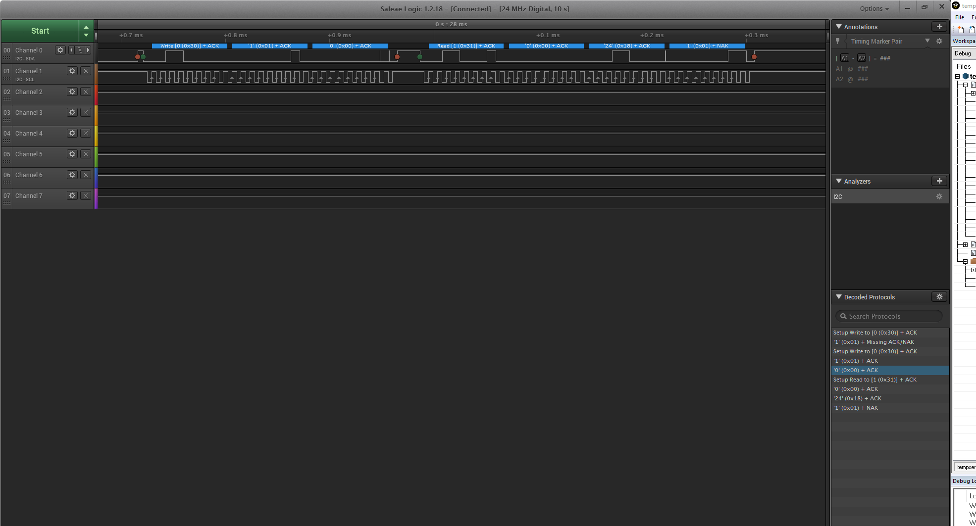
    and read out Addressbyte(0x31), (0x00), (0x08) as a desired result but I am reading out Addressbyte(0x31), (0x00), (0x18), (0x01).

    I have attached results below which are taken by logic analyzer. Any guidance to help me understand where I am doing mistake will be appreciated.

    #define I2C__MSP430FR4133_H_
    
    #include <MSP430.h>
    #include <stdint.h>
    #include <stdio.h>
    #include <string.h>
    #include "usci.h"
    
    #define AMBIENT_TEMPERATURE		0x05
    //#define Configuration_Reg		0x01
    #define DEVICE_ID_REGISTER  		0x04
    #define MANUFACTURE_ID_REGISTER	        0x0054
    //#define AdressByte         	        0x30
    
    
     uint16_t tlen = 0;
     uint16_t rlen = 0;
     int *tx = NULL;
     int *rx = NULL;
     uint8_t addr = 0x18;
    // void *tx =(void *)0x01;
    // void *rx =(void *)0x00;


    volatile unsigned char RXData;
    volatile unsigned char TXData;
    
    long Temperature;
    void Stop_WD (void);
    uint16_t I2C_TempRead(void);
    uint16_t I2C_readMode(void);
    void delay_tick(uint16_t);
    
    
    unsigned char Adressbyte[10]; 
    unsigned char Transmit [10]; 
    unsigned char Meas_Receive [10];
    
    
    int main(void)
    {
     
      Stop_WD();
        
    // Disable the GPIO power-on default high-impedance mode to activate
    // previously configured port settings
    PM5CTL0 &= ~LOCKLPM5; 
    Set_I2C();
    //Transmit [0] =0x30 & 0xFE;
    Transmit [0] = 0x01;
    Transmit [1] = 0x00;
    Transmit [2]=  0x08;
    
    Meas_Receive [0] = 0x07;
    
    
    __bis_SR_register(GIE);
    
    I2C_write(&Transmit[0],1,addr);
    
    delay_tick(500);
    
    Set_I2C();
    
    I2C_write_read (&Transmit[0],2,&Meas_Receive [0],2,addr);
    //I2C_write(&Transmit[0],1,addr);
    //I2C_read(&Meas_Receive [0],2,addr);
    
    I2C_readMode();
    I2C_TempRead();
          
        while (1)
        {
            __delay_cycles(2000);
            while (UCB0CTL1 & UCTXSTP);         // Ensure stop condition got sent
            UCB0CTL1 |= UCTXSTT;                // I2C start condition
          
            __bis_SR_register(LPM0_bits|GIE);   // Enter LPM0 w/ interrupt
        }
    }


    #if defined(__TI_COMPILER_VERSION__) || defined(__IAR_SYSTEMS_ICC__)
    #pragma vector = USCI_B0_VECTOR
    __interrupt void USCIB0_ISR(void)
    #elif defined(__GNUC__)
    void __attribute__ ((interrupt(USCI_B0_VECTOR))) USCIB0_ISR (void)
    #else
    #error Compiler not supported!
    #endif
    {
      switch(__even_in_range(UCB0IV, USCI_I2C_UCBIT9IFG))
      {
        case USCI_NONE:          break;         // Vector 0: No interrupts
        case USCI_I2C_UCALIFG:   break;         // Vector 2: ALIFG
        case USCI_I2C_UCNACKIFG:                // Vector 4: NACKIFG
          UCB0CTL1 |= UCTXSTT;                  // resend start I2C start condition
          break;
        case USCI_I2C_UCSTTIFG:  break;         // Vector 6: STTIFG
        case USCI_I2C_UCSTPIFG:          // Vector 8: STPIFG
         TXData = 0;
         UCB0IFG &= ~UCSTPIFG;                 // Clear stop condition int flag
         break;
        case USCI_I2C_UCRXIFG3:  break;         // Vector 10: RXIFG3
        case USCI_I2C_UCTXIFG3:  break;         // Vector 14: TXIFG3
        case USCI_I2C_UCRXIFG2:  break;         // Vector 16: RXIFG2
        case USCI_I2C_UCTXIFG2:  break;         // Vector 18: TXIFG2
        case USCI_I2C_UCRXIFG1:  break;         // Vector 20: RXIFG1
        case USCI_I2C_UCTXIFG1:           // Vector 22: TXIFG1
    //      UCB0TXBUF = TXData++;
          break; 
        case USCI_I2C_UCRXIFG0:                 // Vector 24: RXIFG0
          RXData = UCB0RXBUF;                   // Get RX data
          __bic_SR_register_on_exit(LPM0_bits); // Exit LPM0
          break;
        case USCI_I2C_UCTXIFG0:  break;         // Vector 26: TXIFG0
        case USCI_I2C_UCBCNTIFG: break;         // Vector 28: BCNTIFG
        case USCI_I2C_UCCLTOIFG: break;         // Vector 30: clock low timeout
        case USCI_I2C_UCBIT9IFG: break;         // Vector 32: 9th bit
        default: break;
      }
    }
    
    void Stop_WD (void)
     {
       WDTCTL = WDTPW | WDTHOLD;                                    // Stop WDT
     }
    //
    //
    //void Device_ID(uint8_t device_reg)
    //{
    // 
    //}
    //
    //void Manufacture_ID(uint8_t manufacture_reg)
    //{
    //  
    //}
    //
    //void Ambient_Temp(uint8_t ambient_temp_reg)
    //{
    //  
    //}                                                                                                                                                                            


    uint16_t I2C_readMode(void)
    {
      uint8_t UpperByte = 0;
      uint8_t LowerByte = 0;
      uint16_t data = 0;
      
    //  UpperByte = i2c_read(); // READ 8 bits
    ////and Send ACK bit
    //LowerByte = i2c_read(); // READ 8 bits
    ////and Send NAK bit
      
     data = UpperByte<<8|LowerByte;
     return data;
    }
    
    uint16_t I2C_TempRead(void)
    {
     uint8_t UpperByte = 0; 
     uint8_t LowerByte = 0;
     uint16_t Temperature = 0;
     
     
     //Convert the temperature data
    //First Check flag bits
    if ((UpperByte & 0x80) == 0x80)
    {                                                       //TA ³ TCRIT
    }
    if ((UpperByte & 0x40) == 0x40)
    {                                                       //TA > TUPPER
    }
    if ((UpperByte & 0x20) == 0x20)
    {                                                       //TA < TLOWER
    }
    UpperByte = UpperByte & 0x1F;                           //Clear flag bits
    
    if ((UpperByte & 0x10) == 0x10)
    {                                                       //TA < 0°C
    UpperByte = UpperByte & 0x0F;                           //Clear SIGN
    Temperature = 256 - (UpperByte * 16 + LowerByte / 16);
    }
    else 
    {                                                       //TA ³ 0°C
    Temperature = (UpperByte * 16 + LowerByte / 16);
                                                            //Temperature = Ambient Temperature (°C)
    }
    return Temperature;
    }
    
    void delay_tick(uint16_t tick)
    {
      for (uint16_t i=0;i<tick; i++);
    }


    //----------------------------------------------I2C--------------------------------//
    
    void Set_I2C(void)
    {
      P5SEL0 |= BIT2 | BIT3;                  // I2C pins
     // Configure USCI_B0 for I2C mode 
      UCB0CTLW0 |= UCSWRST;                   // Software reset enabled
      UCB0CTLW0 |= UCMODE_3 | UCMST | UCSYNC; // I2C mode, Master mode, sync
      UCB0CTLW1 |= UCASTP_2;                  // Automatic stop generated
    
      UCB0BRW = 0x0008;                         // baudrate = SMCLK / 8
      UCB0TBCNT = 0x07;                       // number of bytes to be received
      UCB0I2CSA = 0x18;                       // Slave address is 0x18
      UCB0CTL1 &= ~UCSWRST;
      UCB0IE |= UCRXIE | UCNACKIE | UCBCNTIE ;
      
      
    }


    //------------------I2C_Master_write-------------------------------------------------//
    
    uint32_t I2C_write(unsigned char* tx, uint32_t tlen,uint8_t addr)
    
    {
      uint32_t r_val = 0;
      
      UCB0I2CSA = addr;                             // Assing slave address
      
      while ((UCB0IFG & UCSTPIFG));                 // Check if Stop condition on
      UCB0CTL1 |= UCTR + UCTXSTT;                   // Start writing through I2C
      while (!(UCB0IFG & UCTXIFG));                 // Wait until TX buffer ready
      for(uint32_t i = 0; i < tlen; i++) 
      {           
        UCB0TXBUF = *((uint8_t*)tx + i);            // Write string in  TX buffer of I2C        
        while (!(UCB0IFG & UCTXIFG));               // Wait until TX buffer ready
        if( i == tlen - 1) 
        {                                           // If only one byte left to write
          UCB0CTL1 |= UCTXSTP;                      // I2C stop condition
          UCB0IFG &= ~UCTXIFG;                      // Clear USCI_B0 TX int flag
        }
        r_val++;                                    // Increment return value
      }
    
      return r_val;
    }
    
    //----------------I2C_MASTER_READ--------------------------------------------------------//
    
    uint32_t I2C_read(unsigned char* rx, uint32_t rlen, uint8_t addr)
    
    {
      UCB0IFG &= ~UCSTPIFG;
      uint32_t r_val = 0;
      
      UCB0I2CSA = addr;                               // Assing slave address
      if (rlen != 0)
      {
        while ((UCB0CTL1 & UCTXSTP));                 // Check if Stop condition on
        UCB0CTL1 &= ~UCTR;                            // Set writing bit in register to 0
        UCB0CTL1 |= UCTXSTT;                          // Start reading through I2C
        while (!(UCB0CTL1 & UCTXSTT));                // start condition is not sent
        // only one byte
        if (rlen == 1)
        {
          while (!(UCB0IFG & UCRXIFG))                // wait until start condition is sent
          {
            if((UCB0CTL1 & UCTXSTT)==0)
              UCB0CTL1 |= UCTXSTP;                    // generate stop condition
          }
          while (UCB0CTL1 & UCTXSTP);                 // Ensure stop condition got sent
          *((uint8_t*)rx) = UCB0RXBUF;
          return 1;
        }
        // multiple bytes
        for (uint8_t i = 0; i < rlen-1; i++)
        {
          while (!(UCB0IFG & UCRXIFG));                // Wait until new data was written into RX buffer
          *((uint8_t*)rx + i) = UCB0RXBUF;              // Read RX buffer
          r_val ++;                                     // Increment return value      
        }
        UCB0CTL1 |= UCTXSTP;                            // Generate Stop condition  
        while (UCB0CTL1 & UCTXSTP);                     // Wait untill its generated
        *((uint8_t*)rx+rlen-1) = UCB0RXBUF;             // Read last byte 
      }
      return r_val++;
    }
    
    /*******************/
    
    uint32_t I2C_write_read (unsigned char* tx,uint32_t tlen,unsigned char* rx, uint32_t rlen,uint8_t addr)
    {
      
      uint32_t r_val = 0;
      
      UCB0I2CSA = addr;                             // Assing slave address
      
      while ((UCB0IFG & UCSTPIFG));                 // Check if Stop condition on
      UCB0CTL1 |= UCTR + UCTXSTT;                   // Start writing through I2C
      while (!(UCB0IFG & UCTXIFG));                 // Wait until TX buffer ready
      for(uint32_t i = 0; i < tlen; i++) 
      {           
        UCB0TXBUF = *((uint8_t*)tx + i);            // Write string in  TX buffer of I2C        
        while (!(UCB0IFG & UCTXIFG));               // Wait until TX buffer ready
        if( i == tlen - 1) 
        {                                           // If only one byte left to write
          UCB0CTL1 |= UCTXSTP;                      // I2C stop condition
          UCB0IFG &= ~UCTXIFG;                      // Clear USCI_B0 TX int flag
        }
        r_val++;                                    // Increment return value
      }
      
    r_val = 0;
      
      if (rlen != 0)
      {
        while ((UCB0CTL1 & UCTXSTP));                 // Check if Stop condition on
        UCB0CTL1 &= ~UCTR;                            // Set writing bit in register to 0
        UCB0CTL1 |= UCTXSTT;                          // Start reading through I2C
        while (!(UCB0CTL1 & UCTXSTT));                // start condition is not sent
        // only one byte
        if (rlen == 1)
        {
          while (!(UCB0IFG & UCRXIFG))                // wait until start condition is sent
          {
            if((UCB0CTL1 & UCTXSTT)==0)
              UCB0CTL1 |= UCTXSTP;                    // generate stop condition
          }
          while (UCB0CTL1 & UCTXSTP);                 // Ensure stop condition got sent
          *((uint8_t*)rx) = UCB0RXBUF;
          return 1;
        }
        // multiple bytes
        for (uint8_t i = 0; i < rlen-1; i++)
        {
          while (!(UCB0IFG & UCRXIFG));                // Wait until new data was written into RX buffer
          *((uint8_t*)rx + i) = UCB0RXBUF;              // Read RX buffer
          r_val ++;                                     // Increment return value      
        }
        UCB0CTL1 |= UCTXSTP;                            // Generate Stop condition  
        while (UCB0CTL1 & UCTXSTP);                     // Wait untill its generated
        *((uint8_t*)rx+rlen-1) = UCB0RXBUF;             // Read last byte 
      }
      
      return r_val++; 
    }
    

    Thank you!

    Mr. Shetty

    Student

  • Hi Shetty,

    Can you provide more detail on your issue to me, and the step-by-step explanation of what your code is trying to accomplish?

    I took a look at the datasheet for the MCP9808 - Why are you trying to access the configuration register (0x01) for these results and not the Temperature register (0x05)?

    I recommend taking a step back so we can find out what the issue is here:

    • Verify the pullup resistances and slave address value using the slave device data sheet
    • Check all peripheral initialization, including:
      • Physical pin selection (SDA and SCL)
      • Communication register settings
      • Enabling of interrupts (both local and global)
      • When developing SMBUS communication based on I2C, see SMBUS Design Using MSP430 Design Guide.
    • Use the tools available (for example, IDE debugger, logic analyzer, and oscilloscope) to prove that both ends of the bus are adhering to the I2C software protocol.
    • Review the MSP430 device errata sheet for I2C errata that could be involved.
    • Review the standard I2C examples available in MSP430Ware denoted by ,device>_<usci/eusci>_i2c_standard_.<slave/master>.c

    Here's also a great write up - MSP MCU I2C getting started guide

    -Chris

  • Hi Shetty,

    Have you fixed your issue?

    Please let me know more detail - otherwise, I will assume this this issue is resolved.

    Thanks!
    -Chris

**Attention** This is a public forum