This thread has been locked.

If you have a related question, please click the "Ask a related question" button in the top right corner. The newly created question will be automatically linked to this question.

MSP430G2211: Pin Assignments for Comparator Modules

Part Number: MSP430G2211

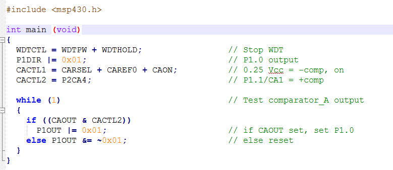
I am having a bit of trouble understanding how to assign a specific pin to a Comparator_A module on msp430g2211. The example code has the following: Now I understand that CACTL1 is assigned to be 0.25*VCC and is on but how do we know it's on the -comp? Also CACTL2 is assigned to P2CA4 which is stated to be P1.1 (or CA1), but how do you know it's P1.1? What if you wanted to use P1.5 to be assigned to CACTL2 which according to the datasheet (see page 6) is CA5?
I looked further into this and found the msp430x2xx family user's guide where on page 531 it explains a bit of the nomenclature but I'm still not very clear on how to assign CACTL2 to specific pins. Help is appreciated!

  • Hello Vijayraj,

    sorry for the misleading code example, which is including even a mistake.

    So please let me bring some light into the Comparator input selection.

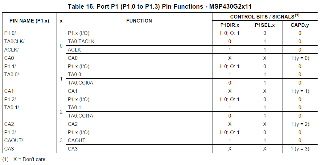
    First let's take at the selection of the Comparator function for P1.1 in the given code example. Let's analyze the multiplexer selection. The P1.1 is equipped with the CA1 function. This is specified in the datasheet table 16.

    The next step is looking into the User's Guide and the input multiplexers in Figure 21-1

    Here you can see, that in case the swap multiplexer control bit CAEX=0 the input for the positive Comparator input is defined by the upper input multiplexer. Looking at the multiplexer options, again you can see to select CA1, you need to set P2CA4 to 1 and P2CA0 to 0.

    That's what is done with the instruction CACTL2 = P2CA4;

    Looking at your question, how to select P1.5 for CACTL2, it's a bit misleading. One has to ask "what pin do you intend to connect to which Comparator input?".

    Let's assume, you want to connect P1.5 to the positive Comparator input. Looking into the datasheet you can see in table 17

    that at P1.5/CA5 is available. Looking again into the block diagram of the User's Guide, you can see the upper multiplexer does not support the connection to CA5. So the only possibility selecting CA5 is using the lower multiplexer. To connect the lower multiplexer to the positive input of the Comparator, you need to set CAEX =1, and to select CA5 the control bits of the multiplexer need to be 101, means P2CA3 = 1, P2CA2 = 0 and P2CA1 = 1.

    To maintain the same functionality as in the given code example now you have to apply the threshold voltage to the negative input, and thus due to CAEX = 1 now CARSEL needs to be = 0. So CACTL1 = CAREF0 + CAON;

    I hope this explanations helps you to understand the complex settings.

    The mistake of the code example I mentioned above, is the missing setting of CAPD for P1.1. This is required to disable the input buffer, to avoid a floating node and respective currents, when applying analog voltage levels to P1.1.

    In your case, you'd need to set it for P1.5.

    Best regards

    Peter

  • Thank you Peter, your explanation makes it very clear.
  • Hello Vijayraj,
    you're welcome. I am happy, being able to solve your problem. For the future just a minor on the E2E system. Please first send your reply, and then click on "resolved my issue", as any post from you after confirming the resolution, will re-open the thread.
    For now I am closing this one, as evidently your problem is solved.

    Best regards
    Peter

**Attention** This is a public forum