Part Number: MSP430F1611
Hello everybody,
I'm actually a bit confused. I'm trying to talk in I2C master mode to a not connected device. It is not connected due to some testing scenarios.
I'm using the following code:
#include <__cross_studio_io.h>
#include <msp430f1611.h>

// ---------------------------------------------------------------------------------------------------------------------
// Variables

int delay_counter = 0;

// ---------------------------------------------------------------------------------------------------------------------
// Main function

void main(void) {

  // Osc
  WDTCTL = WDT_ADLY_1000;                                                       // Watchdog timer 1000 ms
  //IE1 = WDTIE;                                                                  // Enable watchdog interrupt
  BCSCTL1 &= ~XT2OFF;                                                           // Enable oscillator
  do {                                                                          // Delay for external clock
    IFG1 &= ~OFIFG;
    for (delay_counter = 0xFF; delay_counter > 0; delay_counter--);
  } while ((IFG1 & OFIFG) != 0);
  BCSCTL2 = SELM_2 + SELS;                                                      // External clock (8 MHz)

  // Ports
  // USART0 (I2C)
  P3SEL |= (BIT1 + BIT3);                                                       // Peripheral select

  // I2C LEVELSHIFTER
  P4SEL &= ~BIT1;                                                               // I/O select
  P4DIR |= BIT1;                                                                // P4.1 I2C-LEVELSHIFTER as output

  // USART 0
  U0CTL |= SWRST;                                                               // Init USART0 state machine
  U0CTL |= I2C + SYNC;                                                          // I2C mode at USART0
  U0CTL &= ~I2CEN;                                                              // Disable I2C

  // I2C
  I2CTCTL = I2CSSEL_1;                                                          // ACLK clock
  I2CPSC = 0x00;                                                                // Clock precaler /1
  I2CSCLH = 0x0A;                                                               // Shift clock HIGH
  I2CSCLL = 0x0A;                                                               // Shift clock LOW

  // EXPECTING:
  // ACLK = 32 kHz
  // PRESCALED WITH /1 => 32 kHz
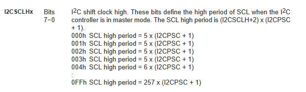
  // HIGH = 5 x (I2CPSC + 1) = 5
  // LOW = 5 x (I2CPSC + 1) = 5
  // COMPLETE PERIOD: 10 => 3.2 kHZ

  // MEASURED: 250 kHz

  I2CNDAT = 0;                                                                  // Initialize with zero bytes
  U0CTL |= I2CEN;                                                               // Enable I2C
  U0CTL |= MST;                                                                 // Master mode for MSP

  I2CIE |= TXRDYIE + ARDYIE;                                                    // Interrupt enable

  P4OUT |= BIT1;                                                                // Enable I2C levelshifter by default

  // I2C write
  while (I2CDCTL & I2CBB);
  I2CSA = 0x1A;                                                                 // Slave address
  I2CNDAT = 0x01;                                                               // Save data lenght

  U0CTL |= MST;                                                                 // Enable master mode
  I2CTCTL |= I2CTRX;                                                            // Transmit mode
  I2CTCTL |= I2CSTT + I2CSTP;                                                   // Start condition and stop condition

  while(1) { };

}

void I2C_ISR(void) __interrupt[USART0TX_VECTOR] {

  switch(I2CIV) {
    case 8:                                                                     // Access ready interrupt
      break;
    case 12:                                                                    // Transmit ready interrupt
      I2CDRB = 0xAA;
      break;
    default:
      break;
  }

}
I'm using two different oscillators on my board. One with 8 MHz at X2IN (MCLK and SMCLK) and a 32.768 Hz oscillator at XIN (ACLK).
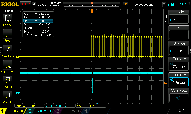
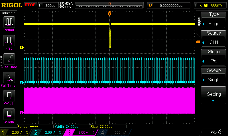
It seems, that it doesn't matter what clock source I am selecting with I2CSSELx, the result always stays the same. The first data on the I2C bus (which is the adress of the device) is clocked with 250 kHz.
Can somebody confirm this behavoir and tell me how to change it for use with the slower clock?