Other Parts Discussed in Thread: MSP-EXP430G2ET
Hello,
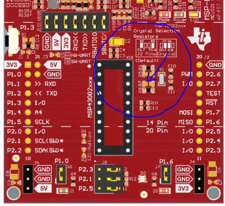
I am trying to blink the onboard LED every one second via a Timer A interrupt, but am failing to understand the logic of specifying the exact interval of the blinking. From what I understand from the users guide, the ACLK is driven directly by the crystal, which oscillates at 32768 Hz. It also says that the TAR increments on every rising edge of the clock signal. So, my immediate thought is that the TAR should overflow after exactly one second if I set the value of the compare register to be 32768, since there is one rising edge per cycle and 32768 cycles in one second. But, with the code I have pasted below, the interrupt triggers roughly every 20 seconds or so. This leads me to believe that the number that should be in TACCR0 is *much* lower than 32768, but I don't know how to calculate it. I'm wondering where my logic is breaking down. I am pretty new to microcontroller development so please forgive me ignorance of electrical engineering related concepts. Please have a look at my code below if you don't mind. Thanks.
#include<msp430g2553.h>

void main(void) {
        // DISABLE WATCHDOG TIMER
        WDTCTL = WDTPW | WDTHOLD;

        // SET TIMER_A CONTROL REGISTER USING ACLK AS CLOCK SRC AND IN UP MODE WITH NO CLOCK DIVISION
        TACTL = TASSEL_1 | MC_1 | ID_0;

        // SET CAPTURE/COMPARE REGISTER TO SPECIFIC VALUE
        TACCR0 |= 0x8000; // 32768 hz, which is the oscillation frequency of aclk

        // SET CAPTURE/COMPARE CONTROL REGISTER TO DICTATE BEHAVIOR OF CAPTURE/COMPARE REGISTER
        // THIS LINE BASICALLY JUST ENABLES INTERRUPTS
        TACCTL0 |= CCIE;

        // MAKE P1.0 AN OUTPUT PIN AND HAVE IT TURNED OFF INITIALLY
        P1DIR |= 0x01;
        P1OUT &= 0x00;

        // ENTER LOW POWER MODE
        // INFORM STATUS REGISTER THAT CPU IS OFF AND GLOBAL INTERRUPTS ARE ENABLED
        _BIS_SR(CPUOFF + GIE);
}

// INTERRUPT SERVICE ROUTINE... TOGGLE LED1 WHENEVER INTERRUPT OCCURS
// I SUSPECT THAT THE MSP430 PLACES THIS ISR IN THE INTERRUPT VECTOR ADDRESS FOR THIS PARTICULAR INTERRUPT
#pragma vector = TIMER0_A0_VECTOR
__interrupt void TIMER0_A0_ISR (void) {
        P1OUT ^= 0x01;
}