Other Parts Discussed in Thread: MSP430F4152
Tool/software: Code Composer Studio
Hello,
I am using MSP430FR6972 Microcontroller.
I am using IRDA program. (IRDA Module : HSDL-4400-031 & HSDL-5400-031) .
There is a customized board, I have to make program according to that board.
I have made partially, actually I am little confused to make full program.
Can you please help me.
PROGRAM:
unsigned char RxByte;
volatile unsigned char RxData[256];
unsigned char TxByte;
volatile unsigned int ir;

void irda();

int main(void)

{
WDTCTL = WDTPW | WDTHOLD; // stop watchdog timer

PJSEL0 = BIT4 | BIT5;
PJDIR = 0xFFFF;

// Configure GPIO
P3SEL0 |= BIT4 | BIT5; // irda operation
P3SEL1 &= ~(BIT4 | BIT5); //irda operation

 PM5CTL0 &= ~LOCKLPM5;

CSCTL0_H = CSKEY >> 8; // Unlock CS registers
CSCTL1 = DCOFSEL_3; // Set DCO to 4MHz
CSCTL2 = SELA__LFXTCLK | SELS__DCOCLK | SELM__DCOCLK;
CSCTL3 = DIVA__1 | DIVS__1 | DIVM__1; // Set all dividers to 1
CSCTL4 &= ~LFXTOFF; // Enable LFXT1
do
{
CSCTL5 &= ~LFXTOFFG; // Clear XT1 fault flag
SFRIFG1 &= ~OFIFG;
}while (SFRIFG1&OFIFG); // Test oscillator fault flag
CSCTL0_H = 0; // Lock CS registers


irda();

while(1)
{

for (ir=1000; ir; ir--); // Small delay
while(!(UCA1IFG & UCTXIFG));
UCA1TXBUF = TxByte;

__disable_interrupt();
UCA1IE |= UCRXIE; // Enable RX int

__bis_SR_register(GIE); // Enter interrupts

LCD[3] = lcd_num[5];
RxData[TxByte] = RxByte; // Store RXed character in RAM
LCD[2] = lcd_num[RxByte];
if (TxByte != RxByte)
{
LCD[0] = lcd_num[8];
while(1);
}
TxByte++;

}
// return 0;
}

void irda()
{
UCA1CTL1 |= UCSWRST;
UCA1CTL1 = UCSSEL_2;            //(0x0080)
UCA1BR0 = 26;
UCA1BR1 = 0;
UCA1MCTLW = UCBRF_1 + UCOS16;
UCA1IRTCTL = UCIRTXPL2 + UCIRTXPL0 + UCIRTXCLK + UCIREN;
UCA1CTL1 &= ~UCSWRST;
UCA1IE |= UCRXIE;
}

INTERRUPT PROGRAM  :

#pragma vector = USCI_A1_VECTOR
__interrupt void USCI_A1_ISR(void)
{
RxByte = UCA1RXBUF; // Get RXed character
UCA1IE &= ~UCRXIE;
}
(I took the reference from MSP430F4152)
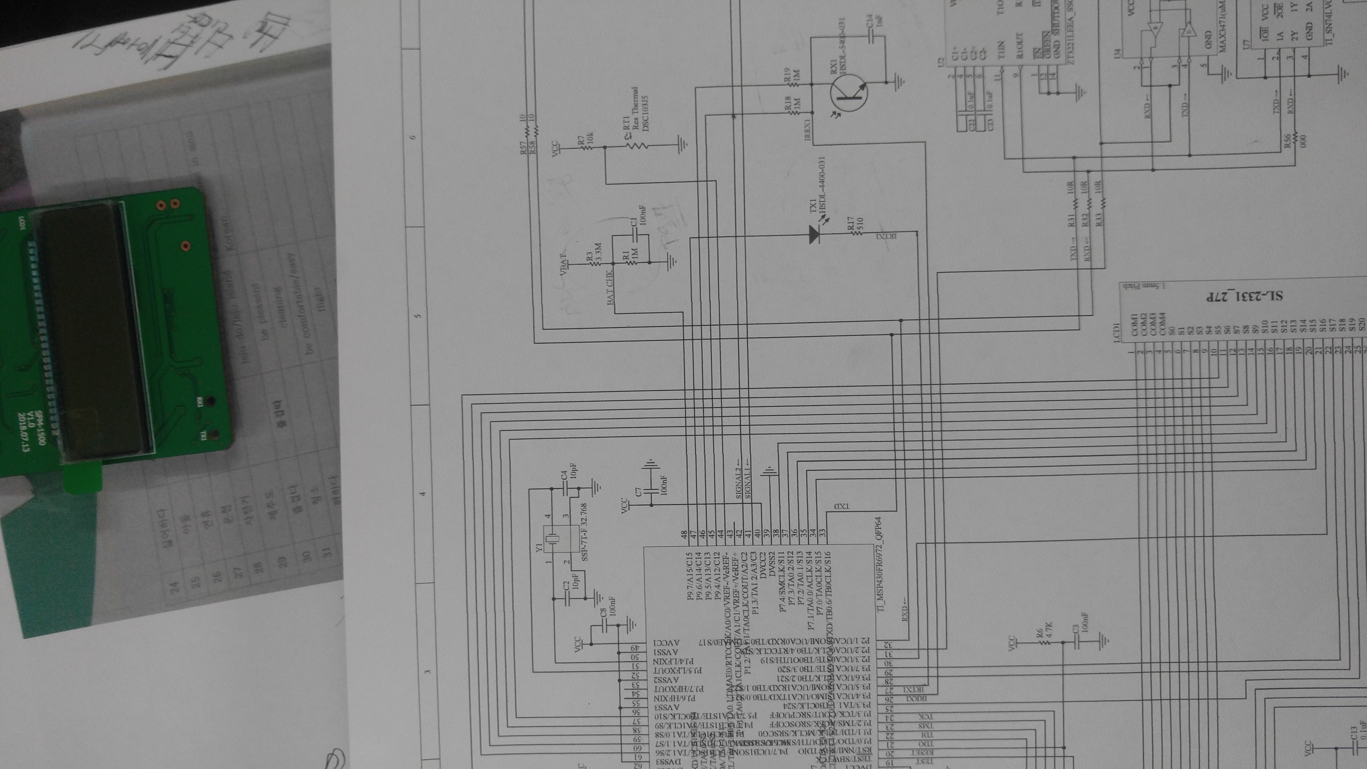
I also upload the circuit.
(In the circuit there are more pins, needs to be added).
Can you please please help me to solve the problem. (any code).
Regards,
Srijit