This thread has been locked.

If you have a related question, please click the "Ask a related question" button in the top right corner. The newly created question will be automatically linked to this question.

MSP430F2012: I2C Slave Application at MSP430F2012

Part Number: MSP430F2012
Other Parts Discussed in Thread: MSP430F169, MSP430FR2422

Hello ...
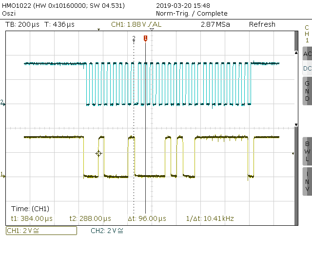
I have a further Question. In my MSP430F2012 I have programmed a I2C Slave Application. At the I2C Bus are more Devices connected. When the master prompts a slave for Data transfer, after the Transfer the 2012-Slave is always in I2C-Interrupts. No action can stop this Interrupts and the program is in endless loop. What can I do to stop the endless loop. I have used an Example from Ti: msp430x20x3_usi_09.s43.
Regards Jurgen

  • Hi Juergen

    You mean you have not change any thing in the example code right? Have you try the same function .c code that is more easy for debug.
  • Hi Gary,

    thank you very much for your response.

    I have changed the code a little bit, but I think this is not the Reason for this behaviour.

    My changes, another Slave Address and not the LMP0-Mode.

    A strange behavior is that I can not delete the "USIIFG" bit. I clear the bit in debug mode and in the same moment it is set again.

    Why can debug better in C?

    The compiler makes an Assembler like the Example.

    Regards Jurgen

                clr.b     &DCOCTL                                        ; Select lowest DCOx and MODx settings

                mov.b  &CALBC1_8MHZ,&BCSCTL1      ; Set DCO to 8MHz

                mov.b  &CALDCO_8MHZ,&DCOCTL

                mov.b  #0xD4,&P1SEL                                ; P1.6 & P1.7 I2C, P1.4 SMCLK, P1.2 TACapture

                mov.b  #0x3B,&P1DIR                                 ; unused pins output direction

                clr.b     &P1OUT                                            ; P1 löschen

                mov.b  #0xc0,&P2DIR                                  ; P2 outputs

                bis.b    #DIVS_3,&BCSCTL2                      ; SMCLK/8

                bis.b    #1,P1OUT                                          ; P1.0 LED ein

                mov     #2,R10

                call      #Delay

                bic.b    #1,P1OUT                                          ; P1.0 LED aus

                mov     #2,R10

                call      #Delay


    ;SetupUSI

                bis.b    #USISWRST,&USICTL0    

                bis.b    #USIPE6+USIPE7,&USICTL0       ; Port, I2C slave

    ;           mov.b  #USIIE+USII2C+USISTTIE,&USICTL1; Enable I2C mode

                mov.b  #USII2C+USISTTIE,&USICTL1   ; Enable I2C mode

                mov.b  #USICKPL,&USICKCTL                ; Setup clock polarity

                bis.b    #USIIFGCC,&USICNT                   ; Disable automatic clear control

                bic.b    #USISWRST,&USICTL0                 ; Enable USI

                bic.b    #USIIFG,&USICTL1                          ; Clear pending flag

                bic.b    #USIOE,&USICTL0                         ; SDA input

                bis.b    #USISCLREL,&USICNT                ; SCL released


    ; Subroutine I2C, I2C Datentransfer

    USI_ISR

    ;-------------------------------------------------------------------------------

    //          mov     #WDTPW + WDTCNTCL + WDTIS0,&WDTCTL                      

                bit.b   #USISTTIFG,&USICTL1    ; Start entry?

                jnc     Check_State

                mov.w   #2,&I2CState             ; First I2C state, Rx address

    Check_State

                add.w   &I2CState,PC          ; I2C State Machine

                jmp     STATE0                      ; I2CState=0

                jmp     STATE2                      ; I2CState=2

                jmp     STATE4                      ; I2CState=4

                jmp     STATE6                      ; I2CState=6

                jmp     STATE8                      ; I2CState=8

                jmp     STATE10                    ; I2CState=10

    ;--------------------------------------------------------------------    

    STATE0

                Nop                                                                ; Idle, should not get here

                bic.b    #USIIFG,&USICTL1                        ; Clear pending flag

                reti

    ;-----------------------------------------------------------------

    STATE2                                                                    ; Receive slave address

                mov.b  &USICNT,R8            ; Bit counter = 8, Rx address

                and.b   #0xE0,R8

                add.b   #0x8,R8

                mov.b  R8,&USICNT

                bic.b    #USISTTIFG,&USICTL1 ; Clear Start flag

                mov     #4,I2CState   ; Go to next state, chk address

                bic.b    #USIIFG,&USICTL1

                reti

    ;--------------------------------------------------------------------       

    STATE4                                             ; Process address and send (N)ack

                mov     #Time_Dat,r12           ; Buffer Zeit und Datum

                bis.b    #USIOE,&USICTL0 ; SDA = output

                mov.b  &USISRL,r9

                rra.b     r9

                cmp.b  #Slave_Adr,r9          ; address match?

                Jnz                                          ;Add_NACK

                clr.b     &USISRL                  ; Send ack

                mov.    #6,I2CState                ; Go to next state: Tx data

                bis.b    #0x01,&USICNT       ; Send Ack bit

                bic.b    #USIIFG,&USICTL1

                reti      


    Add_NACK

    */        

                bis.b    #USIGE+~USIOE,&USICTL0 ; Transparent Latch enabled

                bic.b    #USIGE,&USICTL0 ; Transparent Latch disabled

                clr.w    &I2CState                  ; Reset state machine

                bic.b    #USIIFG,&USICTL1

                reti

    ;----------------------------------------------------------------

    STATE6                                             ; Send data byte

                bis.b    #USIOE,&USICTL0   ; SDA =output

                mov.b  #3,&USISRL             ; send data byte         

    ;           mov.b  @R12+,&USISRL    ; send data byte

                bis.b    #0x8,&USICNT        ; Bit counter = 8

                mov.    #8,I2CState               ; Go to next state, generate stop

                bic.b    #USIIFG,&USICTL1

                reti

    ;----------------------------------------------------------------

    STATE8                                             ; Receive Data (N)Ack

                bic.b    #USIOE,&USICTL0 ; SDA = input

                bis.b    #0x01,&USICNT       ; Receive (N)ack

                mov.    #10,I2CState              ; Go to next state: check (N)ack

                bic.b    #USIIFG,&USICTL1

                reti

    ;-------------------------------------------------------------    

    STATE10

                bic.b    #USIOE,&USICTL0 ; SDA = input

                bit.b     #0x01,&USISRL       ; If Nack received

                jc         Exit

                bic.b    #USIIFG,&USICTL1

                reti

    ;--------------------------------------------------------

    Exit

                clr.       &I2CState      ; Reset state machine

                bic.b    #USIIFG,&USICTL1

                reti      

    END

  • Hi Juergen

    What't the clock frequency do you use in the master? Can you make it slower? And could you capture the waves of SDA and CLK with a logic analyzer?
  • Hi Gery,

    thank you for your answer.

    The Clock I have changed from 8MHz to 1 MHz for the slave. I can capture the SDA and the SCL with my oscilloscope.

               mov.b   &CALBC1_1MHZ,&BCSCTL1   ; Set DCO to 1MHz

               mov.b   &CALDCO_1MHZ,&DCOCTL

    The I2C SCl is 20KHz.

    I have attached a Capturer from a Transfer via I2C.

    Sometimes it is a Deadlock. I can't found this behaviour. Than the SDA is low and the Master can't make someone Transfer. If I start the followed sequence:

    bis.b #USIGE,&USICTL0 ; Output latch always enabled and transparent

    bis.b #USIOE,&USICTL0 ; Output enabled

    bis.b #USIOE,&USICTL0 ; Output disabled

    After this, the SDA goes high. Then the transfer is fine again and data can be transferred again.

    This behavior occurs when there is a transfer to another slave before.

    Regards Jurgen

  • Hi

    Why you delete the STATE12 and STATE12_Exit in our demo code that contain bic.b #USIOE,&USICTL0 to release the SDA?
  • Hi Gary,
    I have found, when the Slave set the SDA low (ACK, NACK I don't know this behaviour), then If I set the SDA to high via the Slave, the I2C Transfer is OK again.
    A very big disadvantage is that I cannot reconfigure the I2C Machine neither from the Slave nor from the Master if its is a deadlock at I2C.
    regards Jürgen
  • Hi

    Have you try our demo code for the slave mode before?
  • Hi Juergen
    One solution here to solve the problem is that you can start a timer when I2C start to transfer data and you can set a maximum time that the transfer will cost and set the SDA if the transfer time exceed the maximum time.
  • Hi Gary,
    I have tested the I2C Transfer with the original Demo Program "msp430x20x3_usi_09.s43" at the MSP430F2012 and a Master at MSP430F169 in very slow Speed. This combination has made not Problems and I have also inserted a Timeout Task.
    A big Problem in my case is, the Slave can’t transfer more as one Byte per "Master read request".
    A further problem, if the slave does not respond immediately (because other tasks have to be done) to the read request, the slave blocks the BUS. Even the Timeout Task can't eliminate the blocking.
    In the User-Guide there is not a flow chart or a state chart how works the I2C module. So I can't me inform about the action from I2C module. I do not know how many Interrupts are called at the Slave per "Master Read request." If I work with Interrupts, the Slave goes in an "endless Interrupt loop".
    I have found, the MSP430F2012 module can't meet the high requirements of a master on an MSP430F1XX or MSP430F54XX.
    Regards Jürgen
  • Hi Juergen

    Due to I have no msp430f2012 now, so it is hard to debug your code examples. But some advises here
    First I will suggest you that you keep the logic state machine in the USI interrupt of the original demo "msp430x20x3_usi_09.s43"
    Second remove the other slave devices to just test the MSP430F2012 as the only slave device.

    Best regards
    Gary
  • Hi Gary
    if I use the MSP430F2012 as the only I2C device (slave), the transfer works. That is not the reality. I would like to use the slave with other I2C slaves (clock, display). The slave should fulfill other tasks besides this I2C function.
    Best regards
    Gary
  • Hi Juergen

    That seems this problem is related with other slave devices. How many other slave devices do you use in your project? Can you solder the slave devices one by one and find the which device made this problem?

    Best regards
    Gary
  • Hi Gary,
    yes, I have all other Devices deactivated and i have also the same problems that I have described before.
    The Slave works only correct, if it is only the Example msp430x20x3_usi_09.s43 running and the Master allways is listen at the slave.
    I can't run an other Task at the Master or the Slave. Than, I have many Timeing Problems.
    Best regards Juergen
  • Hi Juergen

    It is not recommend to change the data processing state machine of the I2C in the demo code. Why you need to change that? What's the gap between the demo code function and your needs? I can give your comments how to change the demo code to meet your application.
  • Hello Gary,

    Many thanks for your help.

    I will send you my program. The program decodes the DCFF77 signal. The time and date I have received can be transferred via the I2C-BUS. The slave opens a time window. During this window, the master can retrieve the time and date.

    The program consists of a C- and an assembler-program. In the assembler-program the I2C transfer is realized. The C program handles the preparation of time and date. Date and time are stored in a structure variable. When the master retrieves time and date, 10 bytes should be transferred.

    The program does not use an interrupt for the I2C transfer.

    The program polls the request of the master by testing the USISTTIFG flag. After the master requests the data, a subroutine in the assembler program is called to transfer the 10 bytes over I2C-BUS.

    DCF77_Stromz_F2012_ass5.rarBest Regards Jurgen

    #include "msp430.h"
    #include "stdbool.h"
    #define high	0xff
    #define low	0
    #define failed  128
    
    /*
    Programm f�r MSP430F2012
    erstellt am 8.10.2018
    Programm im Entwicklungsstatus.
    
    In dem Programm ist die Decodierung des DCF77 Zeitzeichensignals enthalten und eine I2C Slave-Funktion.
    Per I2C Slave kann das ausgewertete Datum und die Zeit abgerufen werden.
    
    Die Erfassung des Zeitsignals per DCF77 geshieht �ber die Auswetung der empfangenen Impulse.
    
    Beim Zeitzeichensignal bedeutet eine Absenkung der Sek.-Impulse auf 100ms ein low Bit,
    eine Absenkung von 200ms ein high Bit.
    
    Die Synchphase beginnt bei der 60. Sek. indem der 60. Sekundenimpuls ausgelassen wird.
    Es wird bis zur 21. Sek. gez�hlt, ab der 21 Sek. wird das Zeitsignal (Impulsl�nge der einzelnen Impulse) ausgewertet.
    Auswerten von "TAvalue" (Impulsmessung)
    entsptechen von "TAvalue" wird ein "low (0)" oder "high (1)" in den Zeit- und Datencode eingetragen.
    */
    
    extern void InitSys(void);
    extern void Transfer_Uhrzeit_Datum(unsigned char *Time_dat);
    extern void Mode1(void);	// Timer1 A Capture aktiv steigende Falnke (Sekundentakt bis 21Sek.)
    extern void Mode2(void);	// Timer1 A Capture aktiv steigende/fallende Falnke (Sekundentakt ab 21Sek.)
    extern void I2C(unsigned char *Time_Dat); // I2C Daten�bertragung
    extern void SetupUSI(void);	// Init I2C
    
    // Time and Date
    struct Time_Dat_
    {
    unsigned char 	MinEin;
    unsigned char	MinZehn;
    unsigned char 	StdEin;
    unsigned char	StdZehn;
    unsigned char 	DayEin;
    unsigned char	DayZehn;
    unsigned char	MonEin;
    unsigned char	MonZehn;
    unsigned char 	YearEin;
    unsigned char	YearZehn;
    } Time_Dat;
    
    extern unsigned int TAvalue;
    static int Impulse=0; 
    static int Bit;
    static int fall=0;
    static bool error=false;
    bool IntTACapture=false;
    static unsigned char *P_Time_Dat;
    
    
    void Read_Time_Date(void)
    {
    //  WDTCTL = WDTPW + WDTCNTCL + WDTIS0;
      switch (Impulse)
      {
       // geht von Bit 1 bis Bit 60. Letztes Daten-Bit Bit 58. Bit 59 Parit�t, Bit 60 Synchronisation
       case 21: if (Bit==high) Time_Dat.MinEin|=1; 
    	    if (Bit==low)  Time_Dat.MinEin&=0xe;  break; // Minute Einer 1
       case 22: if (Bit==high) Time_Dat.MinEin|=2; 
    	    if (Bit==low)  Time_Dat.MinEin&=0xd;  break; // Minute Einer 2
       case 23: if (Bit==high) Time_Dat.MinEin|=4; 
    	    if (Bit==low)  Time_Dat.MinEin&=0xb;  break; // Minute Einer 3
       case 24: if (Bit==high) Time_Dat.MinEin|=8; 
    	    if (Bit==low)  Time_Dat.MinEin&=0x7;  break; // Minute Einer 4
       case 25: if (Bit==high) Time_Dat.MinZehn|=1; 
    	    if (Bit==low)  Time_Dat.MinZehn&=0xe; break; // Minute Zehner 1
       case 26: if (Bit==high) Time_Dat.MinZehn|=2; 
    	    if (Bit==low)  Time_Dat.MinZehn&=0xd; break; // Minute Zehner 2
       case 27: if (Bit==high) Time_Dat.MinZehn|=4; 
    	    if (Bit==low)  Time_Dat.MinZehn&=0xb; break; // Minute Zehner 3
       case 28: break; // Pr�fbit
       case 29: if (Bit==high) Time_Dat.StdEin|=1; 
    	    if (Bit==low)  Time_Dat.StdEin&=0xe;  break; // Stunde Einer 1
       case 30: if (Bit==high) Time_Dat.StdEin|=2; 
        	    if (Bit==low)  Time_Dat.StdEin&=0xd;  break; // Stunde Einer 2
       case 31: if (Bit==high) Time_Dat.StdEin|=4; 
    	    if (Bit==low)  Time_Dat.StdEin&=0xb;  break; // Stunde Einer 3
       case 32: if (Bit==high) Time_Dat.StdEin|=8; 
    	    if (Bit==low)  Time_Dat.StdEin&=0x7;  break; // Stunde Einer 4
       case 33: if (Bit==high) Time_Dat.StdZehn|=1; 
    	    if (Bit==low)  Time_Dat.StdZehn&=0xe; break; // Stunde Zehner 1
       case 34: if (Bit==high) Time_Dat.StdZehn|=2; 
    	    if (Bit==low)  Time_Dat.StdZehn&=0xd; break; // Stunde Zehner 2
       case 35: break; // Pr�fbit          
       case 36: if (Bit==high) Time_Dat.DayEin|=1; 
    	    if (Bit==low)  Time_Dat.DayEin&=0xe;  break; // Tag Einer 1
       case 37: if (Bit==high) Time_Dat.DayEin|=2; 
    	    if (Bit==low)  Time_Dat.DayEin&=0xd;  break; // Tag Einer 2
       case 38: if (Bit==high) Time_Dat.DayEin|=4; 
    	    if (Bit==low)  Time_Dat.DayEin&=0xb;  break; // Tag Einer 3
       case 39: if (Bit==high) Time_Dat.DayEin|=8; 
    	    if (Bit==low)  Time_Dat.DayEin&=0x7;  break; // Tag Einer 4
       case 40: if (Bit==high) Time_Dat.DayZehn|=1; 
    	    if (Bit==low)  Time_Dat.DayZehn&=0xe; break; // Tag Zehner 1
       case 41: if (Bit==high) Time_Dat.DayZehn|=2; 
    	    if (Bit==low)  Time_Dat.DayZehn&=0xd; break; // Tag Zehner 2
       case 42: break; // Wochentag 1
       case 43: break; // Wochentag 2
       case 44: break; // Wochentag 3
       case 45: if (Bit==high) Time_Dat.MonEin|=1; 
    	    if (Bit==low)  Time_Dat.MonEin&=0xe;  break; // Monat Einer 1
       case 46: if (Bit==high) Time_Dat.MonEin|=2; 
    	    if (Bit==low)  Time_Dat.MonEin&=0xd;  break; // Monat Einer 2
       case 47: if (Bit==high) Time_Dat.MonEin|=4; 
    	    if (Bit==low)  Time_Dat.MonEin&=0xb;  break; // Monat Einer 3
       case 48: if (Bit==high) Time_Dat.MonEin|=8; 
    	    if (Bit==low)  Time_Dat.MonEin&=0x7;  break; // Monat Einer 4
       case 49: if (Bit==high) Time_Dat.MonZehn|=1; 
    	    if (Bit==low)  Time_Dat.MonZehn&=0xe; break; // Monat Zehner 1
       case 50: if (Bit==high) Time_Dat.YearEin|=1; 
    	    if (Bit==low)  Time_Dat.YearEin&=0xe; break; // Jahr Einer 1
       case 51: if (Bit==high) Time_Dat.YearEin|=2; 
    	    if (Bit==low)  Time_Dat.YearEin&=0xd; break; // Jahr Einer 2
       case 52: if (Bit==high) Time_Dat.YearEin|=4; 
    	    if (Bit==low)  Time_Dat.YearEin&=0xb; break; // Jahr Einer 3
       case 53: if (Bit==high) Time_Dat.YearEin|=8; 
    	    if (Bit==low)  Time_Dat.YearEin&=0x7; break; // Jahr Einer 4
       case 54: if (Bit==high) Time_Dat.YearZehn|=1;
    	    if (Bit==low)  Time_Dat.YearZehn&=0xe;break; // Jahr Zehner 1
       case 55: if (Bit==high) Time_Dat.YearZehn|=2;
    	    if (Bit==low)  Time_Dat.YearZehn&=0xd;break; // Jahr Zehner 2
       case 56: if (Bit==high) Time_Dat.YearZehn|=4;
    	    if (Bit==low)  Time_Dat.YearZehn&=0xb;break; // Jahr Zehner 3
       // Jahr Zehner 4 und Start    
       case 57: 
          if (Bit==high) 
           {
    	 Time_Dat.YearZehn|=8; Mode1(); fall=0; Impulse=0;
    	 error=false; // kein Fehler
           }
          if (Bit==low) 
           {
    	 Time_Dat.YearZehn&=0x7; Mode1(); fall=0; Impulse=0;         	       
    	 error=false; // kein Fehler
           }
        break;
        default: break;
      }
        Impulse++;
      
    }
    
    int main( void )
    {
      // Stop watchdog timer to prevent time out reset
      WDTCTL = WDTPW + WDTHOLD;
      InitSys();		// Hardware initialisieren
      SetupUSI();
      
    // initialisieren
      Time_Dat.MinEin=0;
      Time_Dat.MinZehn=0;
      Time_Dat.StdEin=0;
      Time_Dat.StdZehn=0;
      Time_Dat.DayEin=0;
      Time_Dat.DayZehn=0;
      Time_Dat.MonEin=0;
      Time_Dat.MonZehn=0;
      Time_Dat.YearEin=0;
      Time_Dat.YearZehn=0;
      Mode1();
      
      TAvalue=0;
      IntTACapture=false;
      while (true)
      {    
    // WatchDog inactive
    // WDTCTL = WDTPW + WDTCNTCL + WDTIS0;
    // polling I2C request of Master
      if (USICTL1 & USISTTIFG) // testen ob Start
      {
        I2C(P_Time_Dat++);
        if (P_Time_Dat>&Time_Dat.YearZehn) P_Time_Dat=&Time_Dat.MinEin;
      }
    // DCF77 Time and Date   
    // Fall 0: Mode2 aktiv, auf 60. Sek. warten, Start
    // Fall 1: auf 21. Sekunde abfragen, ab 21 Sek, Zeitmessung, deshalb steigende und fallende Flanke
    // Interrupt steigende Flanke start Z�hler, Interrupt fallende Flanke stop Z�hler
    // Fall 2: Fall 2 Timer1 fallende Flanke
    // Fall 3: Fall 3 Timer1 steigende Flanke
      if (IntTACapture)
        {  
          IntTACapture=false;
          switch (fall)  
    	      {  
    	      case 0: if (TAvalue>=20000) fall=1;
    		break;
    	      case 1:			// Timer0 A abfragen
    		{
    		   P_Time_Dat=&Time_Dat.MinEin;
    		   // open The Time Window
    		   P1OUT|=2;		// P1.1 setzen, Zeitfenster ein
    		   // if (USICTL1&1==1) USICTL1&=0xfe; 		     
    		   Impulse++;
    		   if (Impulse >= 21)	// 21 Sekund abfragen
    		   {
    		     fall=2; Mode2();
    		     // close the Time Window
    		     P1OUT&=0xFD;	// nach 21. Sek P1.1 l�schen, Zeitfenster aus
    		   } 
    		}
    		break;
    	      case 2:	// Fall 2: Timer1 alle Flanken
    		   if (TAvalue<7000)
    		   {
    		    Bit=failed;		// Bit Fehler
    		    if ((TAvalue<=3800) && (TAvalue>=3000)) Bit=high; // 200ms = 3200Imp
    		    else if ((TAvalue<=1900) && (TAvalue>=1000)) Bit=low; //10ms = 1600Imp
    		    if ((Bit==high) || (Bit==low)) 
    		      Read_Time_Date();		       
    		    else	// if not ((Bit==high) || (Bit==low)) then error und Start
    		      {
    		       error=true;  Mode1(); fall=0; Impulse=0; 
    		      } 
    		   }		// Fall 2:  TAvallue > 3000
    		break;		// case 2 schwitch 1
    		default: break;
    	      }			// end switch 1:   fall
        }
      } //while true
    } // Main
    

  • Hi Juergen

    Thank you for your share. I saw that your assembly code have changed lots with the code you post at begin. Due to I have no msp430f2012 hardware in hand now, so can you help me to capture some waves?
    1. Just sand 0x55 in the I2C(0x55) every 1 seconds or longer to separate every bytes waves;
    2. Change the master CLK frequency at 1k
    3. Capture the waves to sand the 0x55 when the issue, happens.
    I will compare your waves with your codes to see what's wrong with it.

    Best regards
    Gary
  • Hi Gary,
    thank you for your response.
    Yes, the assembly code is different from the one I post at the beginning.
    I have testet many program Versions and I have found the last version that I have posted is the best.
    The I2C SCLK 1KHz that is very slow. OK, I will test with this Clk-frequency.
    regards Juergen
  • Hi Gary,
    I have seen, you also are a specialist for the MSP430FR2422. I use this device to solve my I2C Slave Problem. I think, the eUSCI is a better choin to program an I2C Slave.
    But I have many Problem with this Devices. I can't set P1.0 ... P1.3 as an Output. It seems to be that A0 .. A3 is active. The Outputs at P1.4 .. P1.7 are OK. I have a simple program-Code:
    NAME main ; module name

    PUBLIC main ; make the main label vissible
    ; outside this module
    ORG 0FFFEh
    DC16 init ; set reset vector to 'init' label

    RSEG CSTACK ; pre-declaration of segment
    RSEG CODE ; place program in 'CODE' segment

    init: MOV #SFE(CSTACK), SP ; set up stack

    main: NOP ; main program
    MOV.W #WDTPW+WDTHOLD,&WDTCTL ; Stop watchdog timer
    mov.b #0xff,&P1DIR
    mov.b #0xff,&P2DIR ; P2 Out
    mov.b #0xff,&P2OUT
    loop
    bis.b #1,&P1OUT
    call #Delay
    bic.b #1,&P1OT
    call #Delay
    jmp loop

    Delay
    ....
    .....
    ret
    end

    I have tested 2 Devices, the behavior is all the same. And I have tested with the option P1SEL0=0, P1SEL1=0".
    The signal at P1.0 is always low (floating), 200 ... 260 mV.

    This program runs at IAR IDE 8.0
    Product
    IAR Embedded Workbench for MSP430 IDE, indudi... IAR Embedded Workbench shared components
    Version 7.12.1 8.0.14.5326
  • Hi Juergen

    Goods you solve this issue. The eUSCI is more powerful than the USI.

    Now you have face the configuration of the GPIO function right?

    You can refer to the table here (It is in the datasheet page 52)

    If you want to configure the P1.0..P1.3 to I/O out put mode you should make sure the P1SEL0 and P1SEL1 to 00 at bit 0 1 and 2. And make sure the P1DIR  to 1 at bit 0,1 and 2. Don't configure the ADCPCTLx bit because when you configure that the pin will be configured to analog input no mater what's the value in PIDIR or P1SEL.

  • Hi Gary,

    I have insert a Screenshot from my Debugger. You can see the P1OUT all Pins are high, but at the Device Pins P1.0 ... P1.3 are not a high Voltage Value. It are only 260mV. You can also see the Variable P1DIR, P1SEL0, P1SEL2 and SYSCFG2.

    Regards Jurgen

  • Hi Gary,
    I think I have found the reason, why the ports are not working. If I program the Device and make a power off/on,  after this the Ports are corrupted. I don't know wy this.Than, I clear the Devices with Elprotronic FET and the ports are again OK after a programming. If I make a Power off/on the ports are again always corrupted. This steps I can repeat multiple times.

    Regards Jürgen

  • Hi

    Could down load the code dev.ti.com/.../
    to see if it can works well on P1.0?

    Best regards
    Gary
  • Hi Gary,
    Thank you very much for your help. I hope I can now solve my I2C Slave Problems.
    regards Jurgen

**Attention** This is a public forum