Hi,
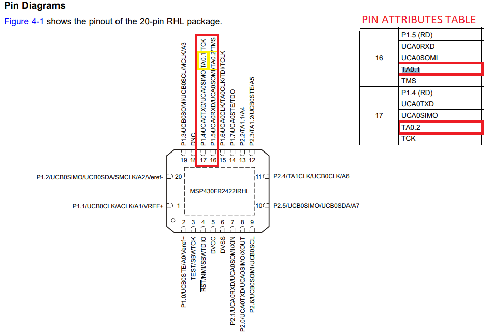
We are planning to use MSP430FR2422IRHLT in one of our designs. Before generating schematic symbol we could find some pin out differences/mismatch in 'PIN DIAGRAMS' view , 'PIN ATTRIBUTES TABLE' and 'SIGNAL TABLE'.
Pin outs are different in the provided datasheet “Pin Diagram view (page 7), PIN Attributes Table(Page8) and Signal Descriptions table (page 10)” for pins (9,10,11,13,16,17). An example screen shot shown below.
Please confirm which Pin out we should follow to build the schematic symbol. It would be better if somebody can list out all the actual functions(multiplexed) of respective above pins.


