
- Ask a related questionWhat is a related question?A related question is a question created from another question. When the related question is created, it will be automatically linked to the original question.

Tool/software: Code Composer Studio
Hi all,
I'm trying to communicate with a SSD1306 OLED screen via I2C. I'm having a problem with the driverlib EUSCI_B_I2C_masterSendMultiByteStart function, it is ignoring the first transmission byte. The only case it actually works is with the default MSP clock (1MHz) and 400kbps for I2C.
I'm configuring the peripheral as follows:
    GPIO_setAsPeripheralModuleFunctionInputPin(GPIO_PORT_P4, GPIO_PIN6 | GPIO_PIN7, GPIO_PRIMARY_MODULE_FUNCTION);

    EUSCI_B_I2C_initMasterParam i2cParam = {0};
    i2cParam.selectClockSource = EUSCI_B_I2C_CLOCKSOURCE_SMCLK;
    i2cParam.i2cClk = CS_getSMCLK();
    i2cParam.dataRate = EUSCI_B_I2C_SET_DATA_RATE_400KBPS;
    i2cParam.byteCounterThreshold = 1;
    i2cParam.autoSTOPGeneration = EUSCI_B_I2C_NO_AUTO_STOP;

    EUSCI_B_I2C_initMaster(EUSCI_B1_BASE, &i2cParam);

    EUSCI_B_I2C_setSlaveAddress(EUSCI_B1_BASE, SSD1306_ADDRESS);

    EUSCI_B_I2C_setMode(EUSCI_B1_BASE, EUSCI_B_I2C_TRANSMIT_MODE);

    EUSCI_B_I2C_enable(EUSCI_B1_BASE);
And I'm using this function to send commands:
void OLED_sendCommand(uint8_t cmd)
{
EUSCI_B_I2C_masterSendMultiByteStart(EUSCI_B1_BASE, 0x00);
EUSCI_B_I2C_masterSendMultiByteNext(EUSCI_B1_BASE, cmd);
EUSCI_B_I2C_masterSendMultiByteStop(EUSCI_B1_BASE);
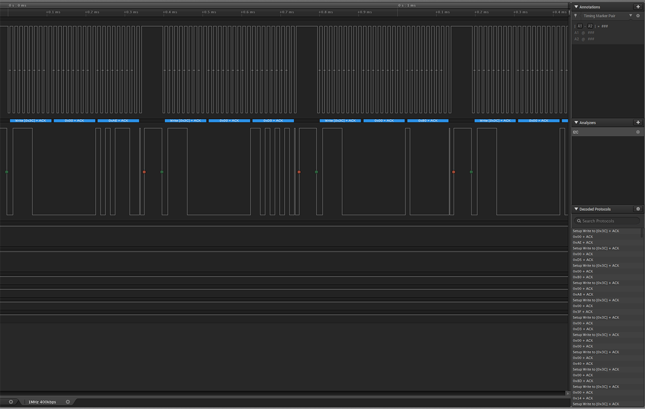
}Now for the outputs, this is using the default clock (1MHz) and 400kbps I2C:
And this is using the default clock (1MHz) with 100kbps I2C:

If I change the I2C clock to 100kbps, or change the system clock to anything but the default 1MHz, EUSCI_B_I2C_masterSendMultiByteStart ignores the first byte. Why is this happening?
Best regards,
Helder Sales


**Attention** This is a public forum


