This thread has been locked.

If you have a related question, please click the "Ask a related question" button in the top right corner. The newly created question will be automatically linked to this question.

CCS/MSP430F5529: MSP430 UART and Ping Sonar Altimeter/Echosounder

Part Number: MSP430F5529


Tool/software: Code Composer Studio

Hey everyone, am working on developing some navigation tools for an underwater project, my main task at this stage is to test the accuracy of an echo-sounder  used to measure the water depth or for more tasks as you can check on the link below where you can find the Ping Sonar that i work with : 

https://www.bluerobotics.com/store/sensors-sonars-cameras/sonar/ping-sonar-r2-rp/

This device have some measurement series that i need to read using UART communication through an MSP430F5529 Launchpad, for doing that i have developed a basic UART driver  as you see below : 

#include <msp430.h>
#include <stdint.h>
#include <stdio.h>
#define TXnotRX  0  //transmitter = 1, receiver = 0
#define loopBack

// char myString[] =  {"A"};
// char *txData = myString;
uint32_t rxData=0;
//char offsetTab = 0;

int main(void)
{
  WDTCTL = WDTPW | WDTHOLD;                 // Stop WDT

  P3SEL |= BIT3 | BIT4;                    // Assign P3.3 to UCA0TXD and...
  P3DIR |= BIT3;                           // P3.4 to UCA0RXD

  UCA0CTL1 |= UCSWRST;                      // **Put state machine in reset**

  UCA0CTL1 |= UCSSEL_1;                     // CLK = ACLK
  UCA0BR0 |= 0x03;                           // 0x0332kHz/9600=3.41 (see User's Guide)
  UCA0BR1 = 0x00;                           //
  UCA0MCTL = UCBRS_3|UCBRF_0;               // Modulation UCBRSx=3, UCBRFx=0

  UCA0CTL1 &= ~UCSWRST;                     // **Initialize USCI state machine**
  UCA0IE |= UCRXIE;                         // Enable USCI_A0 RX interrupt

  __enable_interrupt();

  //while (1){

//#if TXnotRX
//	  UCA0TXBUF = *txData++;
//#endif

  // }


}

// UART ISR
#pragma vector=USCI_A0_VECTOR
__interrupt void USCI_A0_ISR(void)

{
  switch(__even_in_range(UCA0IV, 4))
  {
  case 0:break;                             // Vector 0 - no interrupt
  case 2:                                   // Vector 2 - RXIFG
    while (!(UCA0IFG & UCTXIFG));             // USCI_A0 TX buffer ready?
    rxData = UCA0RXBUF;

//#ifdef loopBack
    // loop back
  //  UCA0TXBUF = UCA0RXBUF;                  // TX -> RXed character
// #endif

    break;
  case 4:break;                             // Vector 4 - TXIFG
  default: break;
  }
}


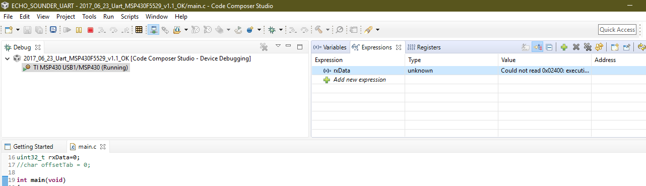
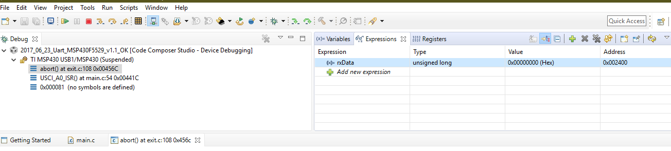
The main problem that i can't read the data in the RX buffer, the output format providing by the sonar is u32, am asking is there any proposition to read the data from the Ping sonar device ?

Regards, 

Zouhir EROUCH,

  • Hello Zouhir,

    At first glance, it appears the UART is initialized properly. Are you able to receive any data from the Ping?

    Based on my understanding of the above, I think you are receiving data but asking how to receive a 32 bit number from the UART. Is this the case? UART sends data as 8 bit characters. So for a 32 bit data value, it would actually take 4 UART transactions. The endianness of the data will be defined by the sensor.

    Thanks,
    JD
  • Hey JD,

    " Are you able to receive any data from the Ping? " : No i still not able to see any data on the " rxData " expression, means that am not receiving the Output of the ping which is an U32 format,

    " I think you are receiving data but asking how to receive a 32 bit number from the UART. Is this the case? " : Unfortunately this is not the case because i still not seen anything related to the ping  

    " The endianness of the data will be defined by the sensor." : i couldn't get your point here? 

    Generally i connect the Ping to my MSP430F5529 using the UART wires, and then i Debug the earlier code and here is where i would like to read the measurement.

    You can see below what i have as a result and the wiring between the two devices :

    This is an image of the wiring :


    When i debug and i resume the executing code i get as result the capture below: 

    And then i click on the halt option i get this : 

    which prove that there is no data to be read on the RX buffer 


    Thank you for any help further, 

    Zouhir EROUCH,

  • Zouhir,

    First, I don't see the ping having a ground connection on the launchpad. Can you double check the wiring there?

    Once the wiring is confirmed, can you scope the data lines from the ping and confirm that it is actually even sending data? Is it just supposed to stream data out, or do you have to do some handshaking first to configure it?

    If you can confirm that it is actually sending data, I would then encourage you to put a break point in your ISR. This way you can see when the interrupt occurred and see exactly what data was read out of the RXBUF.

    Thanks,
    JD
  • Hello JD, 
    The wiring is well checked i have the black wire on the GND pin, am asking now about how to scope the data lines from the ping because this is what i wanted to do ?

  • Hey Zouhir,

    Thanks for re-checking the wiring. To scope the data lines, You should connect them to an oscilloscope or even better would be a logic analyzer.

    You should be able to easily see if there is any data being transferred, measure the BAUD rate, and possibly decode it by hand.

    Once you have this signal capture, please share it here.

    Thanks,
    JD
  • Hey Zouhir,

    Also, I couldn't find my documentation on this Ping device. Do they have a datasheet or document outlining the communication interface?

    I looked briefly at their examples on GIT. They are calling some sort of "initialization" function, although I wasn't able to dig deep enough to look for a source. I imagine they have to first send a command to the sensor to get it to start streaming it's data.

    Thanks,
    JD

**Attention** This is a public forum