This thread has been locked.

If you have a related question, please click the "Ask a related question" button in the top right corner. The newly created question will be automatically linked to this question.

CCS/MSP430FR6972: UART communication issues with TIR1000

Part Number: MSP430FR6972
Other Parts Discussed in Thread: TIR1000

Tool/software: Code Composer Studio

Hello,

I am using MSP430FR6972 with TIR1000.

My plan is to receive data through IRDA(Rx pin of UART1) and send that data to Serial Monitor via 'UART0'.

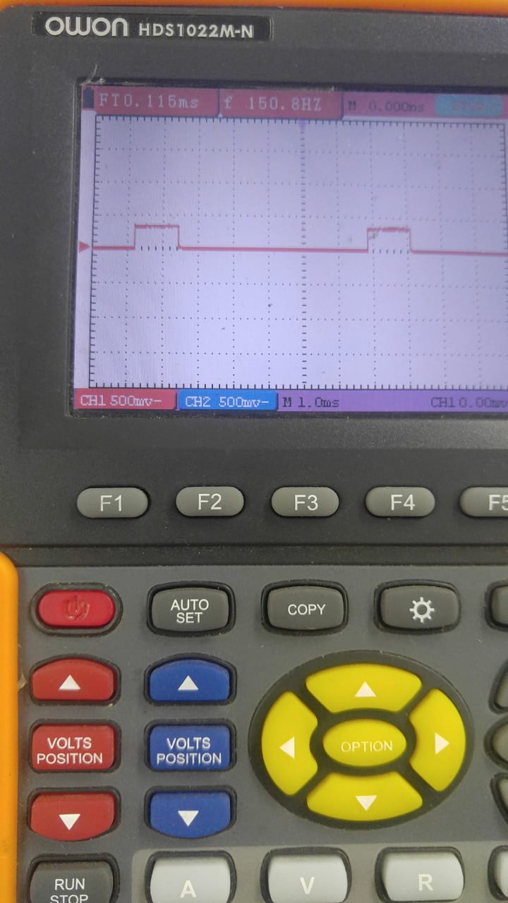
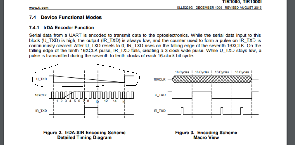
I have used PWM program (P1.0) for 16xclock cycle.

I am trying to receive the program,

but it is not working.

I upload the program below.

Can you please tell me,

what I am doing wrong.?

Regards,

Srijit.

int main(void){
    WDTCTL = WDTPW | WDTHOLD;   // stop watchdog timer

     PJSEL0 = BIT4 | BIT5;
     PJDIR = 0xFFFF;

//IRRx--------------------------
              P1DIR |= BIT0;                     // P1.0 PWM
              P1SEL0 |= BIT0;

//PIN DEFINE===========================================================================

            PM5CTL0 &= ~LOCKLPM5;                   // Disable the GPIO power-on default high-impedance mode


//IRDA================================================================================
  
  
                  CSCTL0_H = CSKEY >> 8;                    
                  CSCTL1 = DCOFSEL_3;
                 CSCTL2 = SELA__LFXTCLK | SELS__DCOCLK | SELM__DCOCLK;               
                 CSCTL3 = DIVA__1 | DIVS__1 | DIVM__1;
                 CSCTL4 &= ~LFXTOFF;
                          do                                        //
                            {                                         //
                              CSCTL5 &= ~LFXTOFFG;                    
                              SFRIFG1 &= ~OFIFG;                       
                            }while (SFRIFG1&OFIFG);                   
                 CSCTL0_H = 0;                             


//       LCD_init();                                                    
         uart_init();                                                   ////UART0


//PWM-------------------------------------------
           TA0CCR0 = 103;                            // PWM Period            ( 104......38400Hz that is 16x clock of 2400)
           TA0CCTL1 = OUTMOD_3;                      // CCR1 reset/set
           TA0CCR1 = 20;                            // CCR1 PWM duty cycle    P1.0 (3/16 LOW)
           TA0CTL = TASSEL__SMCLK | MC__UP | TACLR;  // SMCLK, up mode, clear TAR


      ird_rx() ;

        while(1)
        {
//======IRDA==============================

//------receive-------------------------------------------------------------------
//           putchar('S');
            __bis_SR_register(GIE + LPM3_bits);                                             ////
//              putchar(RxByte);                                                           ////UART0 ....working properly
            __delay_cycles(50000);                                                           ////

       }
//  return 0;
}


IRDA PROGRAM :

void ird_rx(void)                                                                /////transmitting valued----data REAL DATA & Receive not working
{
         P3SEL0 |= BIT5 | BIT4;                    // irda operation RX
        P3SEL1 &= ~(BIT5 | BIT4);
         UCA1CTLW0 |= UCSWRST ;                                                      //Transmitting some values
         UCA1CTL1 |= UCSSEL__SMCLK ;

                    UCA1BR0 = 104;                                                             //2400 /4 mhz
                    UCA1BR1 = 0;
                    UCA1MCTLW |= UCOS16 | UCBRF_3 ;

           UCA1IRTCTL = UCIRTXPL2 + UCIRTXPL0 + UCIRTXCLK  + UCIREN;
           UCA1IRRCTL = UCIRRXPL;
//     UCA1IRCTL = UCIRTXPL2 + UCIRTXPL0 + UCIRTXCLK  + UCIRRXPL + UCIRRXFL2 + UCIRRXFE + UCIREN;

         UCA1CTL1 &= ~UCSWRST ;
         UCA1IE |= UCRXIE;
}


#pragma vector=USCI_A1_VECTOR
__interrupt void USCIA1RX_ISR (void)
{
          RxByte = UCA1RXBUF;
          putchar(RxByte);                     ////UART0 ....TRANSMIT BY UART0
          LPM3_EXIT;
}

  • Hello,
    In above circuit,
    I receive data,
    but some cases it is wrong.
    I receive the value that I am writing below.

    Through another IRDA module I send '0'--- and I receive (my circuit) hex value of BF,
    '1'---- BD,
    '2'--- BB,
    '3'-- BB,
    '4'--B7,
    '5'--B5,
    '6'--B7,
    '7'--B7,
    '8'--BF,
    '9'--BD.
    Can you please tell me, how to solve it.

    Regards,
    Srijit.
  • Hello Srijit,
    have you checked the signals in relation to what you're receiving with your HW? Do you have some scope measurements, which prove the correctness of the incoming signals at the MSP430 in the failure case?

    Best regards
    Peter
  • Hello.

    Thank you very much for your reply.

    Can you check my PWM program,

    I am using 2400BPS.

    IS it ok!!!

    Regards,

    Srijit.

  • Hello Srijit,
    it would be probably faster, more effective and more reliable simply measuring the PWM signal by a scope, than trying to check the PWM by analyzing your code.
    But what is visible from your code:
    You have selected the DCO for SMCLK.
    The SMCLK is selected as clock source for your PWM.
    The Timer is operating in MC__UP mode, which means the Timer runs up to TACCR0 = 103.
    You've stated your desired Baudrate being 2.4kBaud. >> 2.4k * 103 = 247.200kHz DCO frequency required to achieve 2.4kBaud with given Timer settings.

    Best regards
    Peter
  • Hello,

    Thank you for the reply.

    Actually I use the DCO clock (from the reference program of  MSP430FR6972) Dev.TI.

    Can I use any other clock also,

    If I use other clock., what will be the different value.

    I am now doing from the Transmit program with same circuit.

    Program :

    void ird_rx(void);
    void trans(unsigned char DATA);
    
    int main(void)
    {
        WDTCTL = WDTPW | WDTHOLD;	// stop watchdog timer
    
    	 PJSEL0 = BIT4 | BIT5;
    	 PJDIR = 0xFFFF;
    
    
    //IRRx--------------------------
    	          P1DIR |= BIT0;                     // P1.0/TA0.1
    	          P1SEL0 |= BIT0;
    
    //PIN DEFINE===========================================================================
    
    	        PM5CTL0 &= ~LOCKLPM5;                   // Disable the GPIO power-on default high-impedance mode
    
    
    //IRDA================================================================================
    
                      CSCTL0_H = CSKEY >> 8;                    
                      CSCTL1 = DCOFSEL_3;
                     CSCTL2 = SELA__LFXTCLK | SELS__DCOCLK | SELM__DCOCLK;              
                     CSCTL3 = DIVA__1 | DIVS__1 | DIVM__1;
                     CSCTL4 &= ~LFXTOFF;
                              do                                        
                                {                                         
                                  CSCTL5 &= ~LFXTOFFG;                    
                                  SFRIFG1 &= ~OFIFG;                       
                                }while (SFRIFG1&OFIFG);                  
                     CSCTL0_H = 0;                             
    
    //IRDA=========================================================================================
    
    	       TA0CCR0 = 1666;                             ////4000000/2400
    	       TA0CCTL1 = OUTMOD_7 + CCIE;                      // CCR1 reset/set
    	       TA0CCR1 = 833;                                 
    	       TA0CTL = TASSEL__SMCLK | MC__UP | TACLR ;    // SMCLK, up mode, clear TAR
    
        	  ird_rx() ;
    
    	    while(1)
    	    {
    
    
    //-----------------------------------------transmit
    
    	        __bis_SR_register(GIE + LPM3_bits);
    	         if (pattern >0 )
    	        {
    	            pattern=0;                      ////interrupt used for 16x clk : according to data sheet , 16 times of baud rate.
    	            trans('A');
                     }
           }
    //	return 0;
    }
    
    
    void ird_rx(void)                                                                
    {
             P3SEL0 |= BIT5 | BIT4;                    // irda operation RX
             P3SEL1 &= ~(BIT5 | BIT4);
             UCA1CTLW0 |= UCSWRST ;                                                      //Transmitting some values
             UCA1CTL1 |= UCSSEL__SMCLK ;
    
                        UCA1BR0 = 104;                                                             //2400 /4 mhz
                        UCA1MCTLW |= UCOS16 | UCBRF_2 ;
                        UCA1BR1 = 0;
                      
               UCA1IRTCTL = UCIRTXPL2 + UCIRTXPL0 + UCIRTXCLK  + UCIREN;
               UCA1IRTCTL = UCIRRXPL;
    
             UCA1CTL1 &= ~UCSWRST ;
             UCA1IE |= UCRXIE;
    }
    
    void trans(unsigned char DATA)
    {
        while(!(UCA1IFG&UCTXIFG));
         UCA1TXBUF = DATA;
    }
    
    //INTERRUPT USED TO CALCULATE 16xClk = 16 times the Baud rate.
    
    #pragma vector = TIMER0_A1_VECTOR
    __interrupt void Timer0_A1_ISR (void)
    {
    
        if ((P1OUT | BIT0)==1)
               {
                           if(old==0 && condition==0)
                           {
                               start_fl=1;
                           }
                              old=1;
                }
        else
                       {
                              old=0;
                       }
    
    
        if(start_fl)
                          {
                                          if ((P1OUT | BIT0)==1){condition++;}
                                               else{error++;}
    
                                          if (condition > 15) {
                                                             start_fl=0;
                                                             condition=0;
                                                             error =0;
                                                             pattern=1 ;
                                                             LPM3_EXIT; }
                         }
    
     //    LPM3_EXIT;
    }

    And also I am uploading the screen shoot of signal, taken from scope.

    1) I have done  Little change  : SIgnal taken from  PIN No. 1 (16xClk) of TIR1000.

                                                                 TA0CCR0 = 1666;     (4000000/2400 = 1666)  and

                                                                  TA0CCR1 = 833 ;       (50 % PWM)

    I try to get 16xClk .....it is the correct signal ?

    2) Next signal is the IR_TXD signal .

    I took the signal at pin 7 of TIR1000. 

    It is showing some the value at KHz value.

    3) The next signal is taken at U_TXD (pin no. 2 of TIR1000)


    But still transmit is not working.

    regards,

    Srijit

  • Hello peter,

    Did you receive my program and screen shot of Scope.

    Because here I try to open this page ,
    it is showing some error.. like : "score v2 language truncate (srelated thread , subject 120)."

    I do not know , whether you receive or not.
    If yor receive the message ,
    please reply.

    regards,
    Srijit.
  • Hello Srijit,
    sorry for the late response. I had to address other things. I think I can see what you posted, the scope pictures and the additional code you posted on May 14th. I am looking into that. Please give me some time. I'll come back to you as soon as possible.

    Best regards
    Peter
  • Hello Srijit,
    the first scope shot with the square wave signal is showing according to the scope a signal frequency of 2.415kHz. Under the assumption you're trying to transmit and receive at 2.4kBaud, this is not the correct clock frequency for pin 1 16xCLK. So for 2.4kBaud you need to apply here 2.4kHz x 16 = 38.4kHz signal.

    What is the DCO frequency you're targeting. The comments in your code don't say anything about the frequency you're trying to achieve. Keep in mind all timings and signals are derived from the DCO, as long as they use this clock source, so without this information, I cannot judge whether you're selecting a correct approach.

    Best regards
    Peter
  • Thank you very much for your reply.

    Actually I am doing two things.

    1) I am making the PWM signal (SMCLK= 4000000Hz  &  2.4 KHz....as my baud rate is 2400).

    2) With the PWM signal,

    I am trying to get the signal for 16 times first (through  "Timer Interrupt"),

    after that I am trying to transmit the DATA('A').

    (So in timer interrupt ,

    I take a counter of 16   &

    at the end of counter (2400 x  16 = 38400 Hz ),

    I try to transmit DATA.)

     :

    My question :

      If I need to send 38.4 KHz signal through Pin no.1,

       can you tell tell me please, how can I do that through PWM.

      (Please consider that  baud rate is 2400 bps).

    HOW TO TAKE 38.4 KHz using PWM and also with 2400 bps.

    Regards,

    Srijit.


  • Hello Srijit,
    let me try something different to help you.
    On one hand, there is an application report for MSP430FR4xx devices on IR communication. It is actually not IrDA, but there are quite some hints on how to generate signals with Timers/PWMs. Please see www.ti.com/.../slaa644b.pdf
    Secondly the MSP430 USCI with the MSP430FR6972 does have IrDA encoding/decoding support. Please see chapter 30.3.5 IrDA Encoding and Decoding in the MSP430FR6xx User's Guide www.ti.com/.../slau367o.pdf

    Maybe this is of help.

    Best regards
    Peter
  • Hello,

    First of all thank you very much.

    You are correct , that MSP430FR6972 have  have IRDA encoding/decoding support.

    I tried first to make that.

    The transmit part is working.

    But receive part is not working.

    So i choose TIR1000(I thought ,may be with this the module , data may receive).

    SO I choose TIR1000.

    But Now I a stuck with the TIR module.

    I need to make 16x xlk.

    If you can help, it will be a great help for me.

    Regards,

    Srijit.

  • Hello Srijit,
    you stated the receive did not work with the integrated IrDA support in the MSP430. Now as this module is tested and in use since many years, I would assume it works properly. This means the problems either had to be in the code you've implemented, or on the HW side, or on the side of the transmitter.
    I have seen the schematics on the TIR setup, but I have not seen any information on the used transmitter. Could you please share this information? Many thanks in advance.

    Best regards
    Peter
  • Hello,

    Thank you for your reply.

    Which information you want from me ??

    Are you talking about the PIN connection(hardware diagram) or the program??

    (I have already shared it)

    Regards,

    Srijit.

  • Hello Srijit,
    for a point to point communication, you need a device which is transmitting the signal, and a device, which is receiving the signal.

    You have stated the receive did not work. What kind of device has been generating in the case of testing the reception the transmit signal?

    Best regards
    Peter
  • Hello,
    For the communication, I am using another complete transceiver device(purchase it from market).
    I am using that device for receive data/ transmitting data from/to that device from my module.
    The device is working fine itself.
    I just match the baud rate and try to communicate it.

    If you do not mind,
    can you share any Code (Do not refer me to the FR4133, that is based on timer based.)
    [ My requirement is : PWM generated from T0.1 (16xClk)
    And the Tx pin and Rx pin connection (pin connection already uploaded.)

    I you do not mind, can you share c code.

    Thank you in advance.

    Regards,
    Srijit.
  • Hello Srijit,
    in our Code Composer Studio within the Resource Explorer and its code examples, there are multiple code examples for PWM generation.
    msp430fr6x7x_tb0_16.c is demonstrating two PWMs.
    Using ~1MHz
    // SMCLK as TACLK, the timer period is ~1ms with a 75% duty cycle on P1.4
    // and 25% on P1.5.
    // ACLK = n/a, SMCLK = MCLK = TACLK = 1MHz
    It should be easy to change the duty cycle to 50% and the period to your desired value.
    The code is written in C

    Best regards
    Peter
  • Hello,
    thanks for the reply.
    I tried it(pwm), it is giving infinite times of pwm signal.

    Suppose I want it to repeat for 16 times!!

    Can you please tell me...
    how can I do it?
    (PWM for 16 times, ex: pwm set for 9600, then want to make 16xclk)
    I made the PWM, but that is for infinite times.

    So please tell me(16xclk).


    regards,
    srijit.
  • Hello Srijit,
    it is the nature of timer PWM, that it operates after initialization until you stop it by changing the timer settings.
    The previous example on FR4133 is explaining how to handle PWMs using timers. Unfortunately you refused using it.
    There is not other option than counting the PWM cycles and terminating the PWM after the desired number of PWM cycles. Either you perform this action by using a timer, or you use the overflow interrupts of the timer, which is generating the PWM in combination with a counter, counting the PWM periods and again, stopping the PWM after the required number of PWM cycles.

    Best regards
    Peter
  • Hello Srijit,
    I assume you have received enough material on how to debug and resolve this, thus I am suggesting to close this thread.

    Best regards
    Peter
  • Hello,

    The problem is not solved yet.

    Still thank you very much.

    Srijit.

**Attention** This is a public forum