This thread has been locked.

If you have a related question, please click the "Ask a related question" button in the top right corner. The newly created question will be automatically linked to this question.

CCS/MSP430FR2111: MSP430FR2111 current consumption issue after the ADC is closed

Part Number: MSP430FR2111
Other Parts Discussed in Thread: MSP430FR2311, ENERGYTRACE

Tool/software: Code Composer Studio

1 Without using  ADC the power consumption is  around 1.02uA .

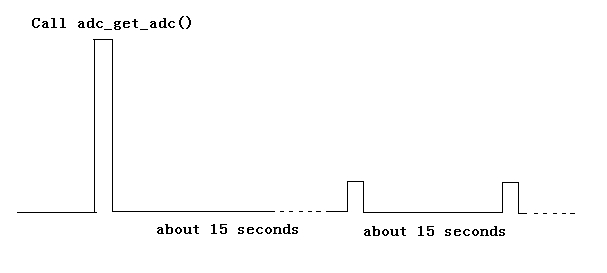
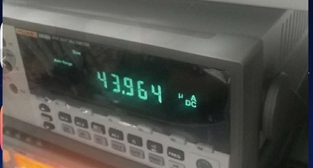
2 My custer closed the ADC after ADC acquisition, but  the CPU power will jump to 43.964 uA. 

My question isHow to reduce the power consumption to 1.02uA?

3 ADC acquisition code is as follow:

uint16_t adc_get_adc(void)
{
    int retry = 10;
    int count = 0;
    uint32_t adc_sum = 0;
    
    ADCCTL0 &= ~ADCENC;                     // Disable ADC
    ADCCTL0 = ADCSHT_2 | ADCON;             // ADCON, S&H=16 ADC clks
    ADCCTL1 = ADCSHP;                       // ADCCLK = MODOSC; sampling timer
    ADCCTL2 = ADCRES;                       // 10-bit conversion results
    //ADCIE = ADCIE0;                         // Enable ADC conv complete interrupt
    ADCIE = 0;
    ADCMCTL0 = ADCINCH_13 | ADCSREF_0;      // A13 ADC input select = 1.5V Ref
                                            // Vref = DVCC
    
    // Configure reference module located in the PMM
    PMMCTL0_H = PMMPW_H;                    // Unlock the PMM registers
    PMMCTL2 |= INTREFEN;                    // Enable internal reference
    while(!(PMMCTL2 & REFGENRDY));          // Poll till internal reference settles
    
    while (retry--) {
        uint16_t adc = 0;
        ADCCTL0 |= ADCENC | ADCSC;
        __no_operation();
        __delay_cycles(1);
        adc = ADCMEM0;
        if (adc > 0) {
          adc_sum += adc;
          count++;
        }
    }
    
    ADCCTL0 &= ~ADCSC;
    ADCCTL0 &= ~ADCENC;
    ADCCTL0 &= ~ADCON;
    ADCCTL1 &= ~ADCSHP;
    ADCMCTL0 &= ~ADCINCH_13;
    
    PMMCTL0_H = PMMPW_H;                        // Unlock the PMM registers
    PMMCTL2 &= ~INTREFEN;                       // Disable internal reference
    PMMCTL2 = 0;
    return count > 0 ? adc_sum / count : 0;
}

Best regards

  • Part Number: MSP430FR2111

    Tool/software: Code Composer Studio

    1. We found that as long as the ADC acquisition code was called, the CPU power would jump, and if the ADC code was not called, there would be no jump. The normal power consumption was maintained at about 1.02uA. The specific ADC acquisition code is as follows, ADC is normally closed after the call, but the power consumption is still jumping. 43uA is the current at the time of jump, approximately 10s from 1.02uA to 43uA, and 43uA is the instantaneous power consumption.

    uint16_t adc_get_adc(void)
    {
        int retry = 10;
        int count = 0;
        uint32_t adc_sum = 0;
        
        ADCCTL0 &= ~ADCENC;                     // Disable ADC
        ADCCTL0 = ADCSHT_2 | ADCON;             // ADCON, S&H=16 ADC clks
        ADCCTL1 = ADCSHP;                       // ADCCLK = MODOSC; sampling timer
        ADCCTL2 = ADCRES;                       // 10-bit conversion results
        //ADCIE = ADCIE0;                         // Enable ADC conv complete interrupt
        ADCIE = 0;
        ADCMCTL0 = ADCINCH_13 | ADCSREF_0;      // A13 ADC input select = 1.5V Ref
                                                // Vref = DVCC
        
        // Configure reference module located in the PMM
        PMMCTL0_H = PMMPW_H;                    // Unlock the PMM registers
        PMMCTL2 |= INTREFEN;                    // Enable internal reference
        while(!(PMMCTL2 & REFGENRDY));          // Poll till internal reference settles
        
        while (retry--) {
            uint16_t adc = 0;
            ADCCTL0 |= ADCENC | ADCSC;
            __no_operation();
            __delay_cycles(1);
            adc = ADCMEM0;
            if (adc > 0) {
              adc_sum += adc;
              count++;
            }
        }
        
        ADCCTL0 &= ~ADCSC;
        ADCCTL0 &= ~ADCENC;
        ADCCTL0 &= ~ADCON;
        ADCCTL1 &= ~ADCSHP;
        ADCMCTL0 &= ~ADCINCH_13;
        
        PMMCTL0_H = PMMPW_H;                        // Unlock the PMM registers
        PMMCTL2 &= ~INTREFEN;                       // Disable internal reference
        PMMCTL2 = 0;
        return count > 0 ? adc_sum / count : 0;
    }

    2 We used the ADC code of the official demo to open the ADC interrupt, but found that we could not enter the interrupt. The attachment is the official downloaded code. I'm using any of these two pieces of code inside.

    slac715d.zip

    3 The sch is as follow:

    sch20190519.pdf


    Best regards

  • Hello,

    According to the datasheet, the typical current consumption when the ADC is active is approximately 200uA for a 3V supply voltage. Please see Table 5-18 in the datasheet for more details.

    Regards,

    James

  • We found that as long as the ADC acquisition code was called, the CPU power would jump, and if the ADC code was not called, there would be no jump. ADC is normally closed after the call, but the power consumption is still jumping.
    We suspect that the ADC did not shut down properly, Please help to analyze it.
    The ADC acquisition code is as follows:

    uint16_t adc_get_adc(void)
    {
    int retry = 10;
    int count = 0;
    uint32_t adc_sum = 0;

    ADCCTL0 &= ~ADCENC; // Disable ADC
    ADCCTL0 = ADCSHT_2 | ADCON; // ADCON, S&H=16 ADC clks
    ADCCTL1 = ADCSHP; // ADCCLK = MODOSC; sampling timer
    ADCCTL2 = ADCRES; // 10-bit conversion results
    //ADCIE = ADCIE0; // Enable ADC conv complete interrupt
    ADCIE = 0;
    ADCMCTL0 = ADCINCH_13 | ADCSREF_0; // A13 ADC input select = 1.5V Ref
    // Vref = DVCC

    // Configure reference module located in the PMM
    PMMCTL0_H = PMMPW_H; // Unlock the PMM registers
    PMMCTL2 |= INTREFEN; // Enable internal reference
    while(!(PMMCTL2 & REFGENRDY)); // Poll till internal reference settles

    while (retry--) {
    uint16_t adc = 0;
    ADCCTL0 |= ADCENC | ADCSC;
    __no_operation();
    __delay_cycles(1);
    adc = ADCMEM0;
    if (adc > 0) {
    adc_sum += adc;
    count++;
    }
    }

    ADCCTL0 &= ~ADCSC;
    ADCCTL0 &= ~ADCENC;
    ADCCTL0 &= ~ADCON;
    ADCCTL1 &= ~ADCSHP;
    ADCMCTL0 &= ~ADCINCH_13;

    PMMCTL0_H = PMMPW_H; // Unlock the PMM registers
    PMMCTL2 &= ~INTREFEN; // Disable internal reference
    PMMCTL2 = 0;
    return count > 0 ? adc_sum / count : 0;
    }
  • Hi,

    Could you give me more information about the test/running condition of the two different power consumption?
  • Hi Wei.Jetim,

         Thanks for ur repley.

    1  The power jump depends on whether the function adc_get_adc() is called. If the function is called, there will be a power jump. If it is not called, there will be no power jump.

    2 See the attachment for the code details

    /* --COPYRIGHT--,BSD
     * Copyright (c) 2017, Texas Instruments Incorporated
     * All rights reserved.
     *
     * Redistribution and use in source and binary forms, with or without
     * modification, are permitted provided that the following conditions
     * are met:
     *
     * *  Redistributions of source code must retain the above copyright
     *    notice, this list of conditions and the following disclaimer.
     *
     * *  Redistributions in binary form must reproduce the above copyright
     *    notice, this list of conditions and the following disclaimer in the
     *    documentation and/or other materials provided with the distribution.
     *
     * *  Neither the name of Texas Instruments Incorporated nor the names of
     *    its contributors may be used to endorse or promote products derived
     *    from this software without specific prior written permission.
     *
     * THIS SOFTWARE IS PROVIDED BY THE COPYRIGHT HOLDERS AND CONTRIBUTORS "AS IS"
     * AND ANY EXPRESS OR IMPLIED WARRANTIES, INCLUDING, BUT NOT LIMITED TO,
     * THE IMPLIED WARRANTIES OF MERCHANTABILITY AND FITNESS FOR A PARTICULAR
     * PURPOSE ARE DISCLAIMED. IN NO EVENT SHALL THE COPYRIGHT OWNER OR
     * CONTRIBUTORS BE LIABLE FOR ANY DIRECT, INDIRECT, INCIDENTAL, SPECIAL,
     * EXEMPLARY, OR CONSEQUENTIAL DAMAGES (INCLUDING, BUT NOT LIMITED TO,
     * PROCUREMENT OF SUBSTITUTE GOODS OR SERVICES; LOSS OF USE, DATA, OR PROFITS;
     * OR BUSINESS INTERRUPTION) HOWEVER CAUSED AND ON ANY THEORY OF LIABILITY,
     * WHETHER IN CONTRACT, STRICT LIABILITY, OR TORT (INCLUDING NEGLIGENCE OR
     * OTHERWISE) ARISING IN ANY WAY OUT OF THE USE OF THIS SOFTWARE,
     * EVEN IF ADVISED OF THE POSSIBILITY OF SUCH DAMAGE.
     * --/COPYRIGHT--*/
    //******************************************************************************
    //  MSP430FR2000 Demo - RTC, Interrupt Host at Predetermined Time
    //
    //  Description: Configure ACLK to use XT1 as RTC source clock,
    //               ACLK = XT1 = ~32768kHz, MCLK = SMCLK = default DCODIV = ~1MHz.
    //
    //           MSP430FR2000
    //         ---------------
    //     /|\|               |
    //      | |               |
    //      --|RST            |
    //        |          P1.0 |---> Host (Interrupt Host)
    //        |               |
    //        |          P1.1 |<--  外部中断唤醒
    //        |               |
    //        |           P2.6|--> XOUT 32768 XTAL
    //        |           P2.7|<-- XIN
    //
    //   Jace Hall
    //   Texas Instruments Inc.
    //   July 2017
    //   Built with Code Composer Studio v7.2 and IAR 7.10
    //******************************************************************************
    #include <msp430.h>
    #include <stdint.h>
    #include <string.h>
    
    uint16_t adc_get_adc(void);
    
    #pragma pack(1) 
    
    typedef struct
    {
        uint8_t step_en_u;        //间隔上传开关
        uint16_t step_time_u;      //间隔时间,单位分钟。每天0点开始。
        uint8_t point_en_u;       //定点上传开关
        uint32_t point_list_u;    //位结构,定点时刻,单位小时
    	
    	uint8_t step_en_s;        //间隔采集开关
        uint16_t step_time_s;      //间隔时间,单位分钟。每天0点开始。
        uint8_t point_en_s;       //定点采集开关
        uint32_t point_list_s;    //位结构,定点时刻,单位小时
        
    }sWakeUpParam_t;
    
    typedef enum
    {
     SYS_MODE_NORMAL        =  0x00,  //正常休眠模式
     SYS_MODE_POINT_U       =  0x01,  //定点唤醒模式(只上传)
     SYS_MODE_STEP_U        =  0x02,  //间隔唤醒模式(只上传)
     SYS_MODE_MOVE          =  0x04,  //异动唤醒模式(采集+上传)
     SYS_MODE_POINT_S       =  0x08,  //定点唤醒模式(只采集)
     SYS_MODE_STEP_S        =  0x10,  //定点唤醒模式(只采集)
     
    }eSysMode_t;
    
    typedef struct
    {
        uint8_t  is_set;         //是否被初始化
        uint32_t last_min_time;
        uint32_t last_hour_time;
    } Dev_Upload_t;
    
    typedef struct
    {
      eSysMode_t   sys_mode;
      uint32_t     start_tick; //总时间的
      Dev_Upload_t upload;
      Dev_Upload_t sample;
      uint32_t   tick;  
    }s_DevInfo;
    
    
    typedef struct time {
    	uint8_t sec;         /* seconds */
    	uint8_t min;         /* minutes */
    	uint8_t hour;        /* hours */
    	uint8_t day;        /* day of the month */
    	uint8_t mon;         /* month */
    	uint16_t year;        /* year */
    	uint8_t week;        /* day of the week */
    } Time_t;
    
    #pragma pack()
    
    /* Global Variables */
    #if defined(__IAR_SYSTEMS_ICC__)
    //__persistent volatile unsigned char timeIncrement = 0; //Software Count Variable
    __persistent volatile  sWakeUpParam_t WakeUpParam;
    //__persistent volatile uint32_t led_flag = 0;
     #elif defined(__TI_COMPILER_VERSION__)
    #pragma PERSISTENT(timeIncrement)
    volatile unsigned char timeIncrement = 0;              //Software Count Variable
    #endif
    
    
    static volatile uint32_t timeStamp = 0;  //定义时间戳,每隔2s中加一次
    
    static uint16_t adc_result = 0;
    static uint16_t adc_ide = 0;
    
    
    #define UART_BUF_MAX 32
    static uint8_t uart_index = 0, uart_data[UART_BUF_MAX] = {0};
    static volatile uint32_t  jiffies = 0;
    static volatile uint16_t  stop_mode_sec = 0;
    
    __no_init uint8_t  data, led_flag, port2_flag,port1_flag;
    
    #define MSP430_VER '1'
    
    #define SDDCP_PRE_1             0xff
    #define SDDCP_PRE_2             0xfe  /* "##" */
    
    #define RESPON_CODE_SUCCESS (0X00)
    #define RESPON_CODE_ERROR   (0X01)
    
    #define SDCCP_TYPE_REQUEST (0x00)
    #define SDCCP_TYPE_RESPONS (0x01)
    
    
    #define COMMAND_TIME_SET       (0x00)  //请求对时
    #define COMMAND_TIME_GET       (0x01)  //获取时间
    #define COMMAND_WKAEUP_MODE    (0x02)  //查询唤醒模式
    #define COMMAND_POWER_OFF      (0x03)  //关闭BC26电源
    #define COMMAND_SET_PARM       (0x04)  //设置参数
    #define COMMAND_GET_PRAM       (0x05)  //获取参数
    #define COMMAND_GET_ADC        (0X06)  //获取电池电压
    #define COMMAND_DELAY_POWEROFF (0X07) //延迟关机
    #define COMMAND_STOPMODE_SET   (0x08) //停机设置,单位s


    /* Constant Definitions */
    #define INCREMENT 0  // Software Count Interval, change this to increase
                         // Wake-up Time.
    /**
     * RTC Count Initialization
     * 1024/32768 * 32 = 1 sec.
     * 30 minutes = 1800 sec. 1800 *32 = 57,600. (57600-1) to hex = 0xE0FF.
     * Wake-up in seconds is equal to (RTCMOD/32) * INCREMENT
     */
    #define MODCOUNT (32*2-1) //Value of RTCMOD Register. //Every 32 counts is 1 second. Value 0xE0FF is 30 minutes
    
    #define BC26_POWER_ON()    do { if(!stop_mode_sec) {adc_ide = adc_get_adc(); P1OUT &= ~BIT5;} } while (0)
    #define BC26_POWER_OFF()   P1OUT |= BIT5
    
    
    #define LED_ON()       P1OUT  &= ~BIT0
    #define LED_OFF()      P1OUT  |= BIT0
    #define LED_TOGGLE()   P1OUT ^= BIT0
    
    #define SYS_MAX_TIME_OUT (60)    //异动情况下,BC26电源打开后,无操作2分钟,关闭电源。
    #define POWEROFF_MAX_TIME_OUT (60*5)    //即使进行了延时关闭,无操作10分钟,关闭电源。
    #define SYS_CFG_TIME_OUT (15)    //配置模式下,BC26电源打开后,无操作5分钟,关闭电源。目前处于调试模式,设置短一些


    static s_DevInfo g_xDevInfo;
    
    
    void UART_sendByte(uint8_t txByte);
    
    
    static uint8_t get_check_sum(uint8_t *pdata, uint32_t len)
    {
      int i = 0;
      int check_sum = 0;
      for(i = 0 ; i < len; i++){
        check_sum += pdata[i];
      }
      return (uint8_t)(check_sum & 0xff);
    }
    
    static void uart_respon_ack(uint8_t command,  uint8_t respone_code)
    {
      uint8_t buf[32] = {0};
      uint8_t index = 0;
      buf[index] = SDDCP_PRE_1; index++;
      buf[index] = SDDCP_PRE_2; index++;
      
      
      buf[index] = SDCCP_TYPE_RESPONS; index++;
      buf[index] = command; index++;
      
      buf[index] = 1;  index++;
      buf[index] = respone_code;  index++;
      buf[index] = get_check_sum(buf,index);
      index++;
      for(int i = 0; i < index; i++){
        UART_sendByte(buf[i]);
      }
    }
    
    static void uart_respon_data(uint8_t command, void *pdata,uint8_t len)
    {
      uint8_t buf[32] = {0};
      uint8_t index = 0;
      buf[index] = SDDCP_PRE_1; index++;
      buf[index] = SDDCP_PRE_2; index++;
      buf[index] = SDCCP_TYPE_RESPONS; index++;
      buf[index] = command; index++;
      
      buf[index] = len; index++;
    
      memcpy(&buf[index],pdata,len); index+=len;
      
      buf[index] = get_check_sum(buf,index);
      index++;
      
      for(int i = 0; i < index; i++){
        UART_sendByte(buf[i]);
      }
    }
    
    static void GregorianDay(struct time *tt)
    {
    	int leapsToDate;
    	int lastYear;
    	int day;
    	int MonthOffset[] = { 0, 31, 59, 90, 120, 151, 181, 212, 243, 273, 304, 334 };
    
    	lastYear = tt->year - 1;
    
    	leapsToDate = lastYear / 4 - lastYear / 100 + lastYear / 400;
    
    	if ((tt->year % 4 == 0) &&
    			((tt->year % 100 != 0) || (tt->year % 400 == 0)) &&
    			(tt->mon > 2)) {
    		/*
    		* We are past Feb. 29 in a leap year
    		*/
    		day = 1;
    	} else {
    		day = 0;
    	}
    
    	day += lastYear * 365 + leapsToDate + MonthOffset[tt->mon - 1] + tt->day;
    
    	tt->week = day % 7;
    
    	if (tt->week == 0) {
    		tt->week = 7;
    	}
    }
    
    /*
    static uint32_t date_to_sec(struct time *tt)
    {
    	uint32_t a1 = tt->year, a2 = tt->mon, a3 = tt->day, a4 = tt->hour, a5 = tt->min, a6 = tt->sec;
    
    	uint32_t z = (14 - a2) / 12;
    	uint32_t y = a1 + 4800 - z;
    	uint32_t m = a2 + 12 * z - 3;
    	uint32_t j = (153 * m + 2) / 5 + a3 + y * 365 + y / 4 - y / 100 + y / 400 - 2472633;
    	j = j * 86400 + a4 * 3600 + a5 * 60 + a6;
    
    	return j ;
    }*/
    
    
    static void sec_to_date(uint32_t timestamp , struct time *tt)
    {
    
    	uint32_t t = timestamp;
    
    	int yy, mm, dd, hh, nn, ss;
    	int a, b, c, d, e, m;
    
    	ss =  t % 60;
    	t /= 60;
    	nn = t % 60;
    	t /= 60;
    	hh = t % 24;
    	dd = t / 24;
    	t /= 24;
    	a = t + 2472632;
    	b = (4 * a + 3) / 146097;
    	c = (-b * 146097) / 4 + a;
    	d = (4 * c + 3) / 1461;
    	e = (-1461 * d) / 4 + c;
    	m = (5 * e + 2) / 153;
    	dd = -(153 * m + 2) / 5 + e + 1;
    	mm = -m / 10 * 12 + m + 3;
    	yy = b * 100 + d - 4800 + m / 10;
    
    	tt->year = yy ;
    	tt->mon  = mm ;
    	tt->day  = dd ;
    	tt->hour = hh ;
    	tt->min  = nn ;
    	tt->sec  = ss ;
    	GregorianDay(tt);
    
    	return ;
    }
    
    static int das_time_get_day_min(uint32_t timestamp)
    {
       struct time  lt;
       sec_to_date(timestamp, &lt);
       return lt.hour * 60 + lt.min;
    }
    
    static int das_time_get_hour(uint32_t timestamp)
    {
        struct time lt;
        sec_to_date(timestamp, &lt);
        return lt.hour;
    }
    
    static int das_time_is_sync(void)
    {
        return (timeStamp >= 1514736000);
    }
    
    static int is_point_upload(void)
    {
       int hour = das_time_get_hour(timeStamp);
       int i;
       for(i = 0 ; i < 24; i++){
    		if((hour == i) && (WakeUpParam.point_list_u & (1<<i)) ) return 1;
       }
       return 0;
    }
    
    static int is_point_sample(void)
    {
       int hour = das_time_get_hour(timeStamp);
       int i;
       for(i = 0 ; i < 24; i++){
        if((hour == i) && (WakeUpParam.point_list_s & (1<<i)) ) return 1;
       }
       return 0;
    }
    
    
    static void check_dev_status(void)
    {
      
      /*if( (g_xDevInfo.sys_mode == SYS_MODE_MOVE) && (jiffies - g_xDevInfo.tick == SYS_TIME_OUT)){
          g_xDevInfo.sys_mode = SYS_MODE_BC26_POWERON;  //20s后关闭调试灯,进入BC26电源打开模式,此时设备处于低功耗休眠模式。
          g_xDevInfo.tick = jiffies; 
          LED_OFF();
      }*/
      
      //间隔采集检测
      if(das_time_is_sync() && WakeUpParam.step_en_s && g_xDevInfo.sample.is_set){
          if((das_time_get_day_min(g_xDevInfo.sample.last_min_time)/WakeUpParam.step_time_s) != (das_time_get_day_min(timeStamp)/WakeUpParam.step_time_s)) {
                g_xDevInfo.sys_mode |= SYS_MODE_STEP_S;
                g_xDevInfo.tick = jiffies;
                g_xDevInfo.start_tick = jiffies;
                LED_ON();
                BC26_POWER_ON();
                g_xDevInfo.sample.last_min_time = timeStamp;
          }
      }
    
    //定点采集监测
       if(das_time_is_sync() && WakeUpParam.point_en_s && g_xDevInfo.sample.is_set){
          if(das_time_get_hour(g_xDevInfo.sample.last_hour_time) != das_time_get_hour(timeStamp)) {
               if(is_point_sample() ){
                    g_xDevInfo.sys_mode |= SYS_MODE_POINT_S;
                    g_xDevInfo.tick = jiffies;
                    g_xDevInfo.start_tick = jiffies;
                    LED_ON();
                    BC26_POWER_ON();
                    g_xDevInfo.sample.last_hour_time =  timeStamp;
              }
          }
        }


    //间隔上传检测
      if(das_time_is_sync() && WakeUpParam.step_en_u && g_xDevInfo.upload.is_set){
          if((das_time_get_day_min(g_xDevInfo.upload.last_min_time)/WakeUpParam.step_time_u) != (das_time_get_day_min(timeStamp)/WakeUpParam.step_time_u) ) {
                g_xDevInfo.sys_mode |= SYS_MODE_STEP_U;
                g_xDevInfo.tick = jiffies;
                g_xDevInfo.start_tick = jiffies;
                LED_ON();
                BC26_POWER_ON();
                g_xDevInfo.upload.last_min_time = timeStamp;
          }
      }
    
    //定点上传监测
       if(das_time_is_sync() && WakeUpParam.point_en_u && g_xDevInfo.upload.is_set){
          if(das_time_get_hour(g_xDevInfo.upload.last_hour_time) != das_time_get_hour(timeStamp)) {
               if(is_point_upload() ){
                    g_xDevInfo.sys_mode |= SYS_MODE_POINT_U;
                    g_xDevInfo.tick = jiffies;
                    g_xDevInfo.start_tick = jiffies;
                    LED_ON();
                    BC26_POWER_ON();
                    g_xDevInfo.upload.last_hour_time = timeStamp;
              }
          }
        }
      
      if( (g_xDevInfo.sys_mode != SYS_MODE_NORMAL)  && (jiffies - g_xDevInfo.tick >= SYS_MAX_TIME_OUT)  ){
          g_xDevInfo.tick = jiffies;     //打开BC26电源后,最多1分钟没有通过串口关闭电源,主动关闭BC26电源
          LED_OFF();
          BC26_POWER_OFF();
          g_xDevInfo.sys_mode = SYS_MODE_NORMAL;
      }
      
      //进行了延时关闭430,最大10分钟关闭msp430
       if( (g_xDevInfo.sys_mode != SYS_MODE_NORMAL)  && (jiffies -  g_xDevInfo.start_tick >= POWEROFF_MAX_TIME_OUT)  ){
          g_xDevInfo.tick = jiffies;     //打开BC26电源后,最多10分钟没有通过串口关闭电源,主动关闭BC26电源
          g_xDevInfo.start_tick = jiffies;
          LED_OFF();
          BC26_POWER_OFF();
          g_xDevInfo.sys_mode = SYS_MODE_NORMAL;
      }
    
      
      /*if( (g_xDevInfo.sys_mode == SYS_MODE_CFG) && (jiffies - g_xDevInfo.tick >= SYS_CFG_TIME_OUT) ){
          g_xDevInfo.tick = jiffies;     //配置模式下打开BC26电源后,最多5分钟没有通过串口关闭电源,主动关闭BC26电源
          LED_OFF();
          BC26_POWER_OFF();
          g_xDevInfo.sys_mode = SYS_MODE_NORMAL;
      }*/
      
    }
    
    /*
    void vAdcInit(void)
    {
        // Configure ADC
        ADCCTL0 &= ~ADCENC;                     // Disable ADC
        ADCCTL0 = ADCSHT_2 | ADCON;             // ADCON, S&H=16 ADC clks
        ADCCTL1 = ADCSHP;                       // ADCCLK = MODOSC; sampling timer
        ADCCTL2 = ADCRES;                       // 10-bit conversion results
        //ADCIE = ADCIE0;                         // Enable ADC conv complete interrupt
        ADCIE = 0;
        ADCMCTL0 = ADCINCH_13 | ADCSREF_0;      // A13 ADC input select = 1.5V Ref
                                                // Vref = DVCC
    }*/
    
    
    uint16_t adc_get_adc(void)
    {
        int retry = 10;
        int count = 0;
        uint32_t adc_sum = 0;
        
        ADCCTL0 &= ~ADCENC;                     // Disable ADC
        ADCCTL0 = ADCSHT_2 | ADCON;             // ADCON, S&H=16 ADC clks
        ADCCTL1 = ADCSHP;                       // ADCCLK = MODOSC; sampling timer
        ADCCTL2 = ADCRES;                       // 10-bit conversion results
        //ADCIE = ADCIE0;                         // Enable ADC conv complete interrupt
        ADCIE = 0;
        ADCMCTL0 = ADCINCH_13 | ADCSREF_0;      // A13 ADC input select = 1.5V Ref
                                                // Vref = DVCC
        
        // Configure reference module located in the PMM
        PMMCTL0_H = PMMPW_H;                    // Unlock the PMM registers
        PMMCTL2 |= INTREFEN;                    // Enable internal reference
        while(!(PMMCTL2 & REFGENRDY));          // Poll till internal reference settles
        
        while (retry--) {
            uint16_t adc = 0;
            ADCCTL0 |= ADCENC | ADCSC;
            __no_operation();
            __delay_cycles(1);
            adc = ADCMEM0;
            if (adc > 0) {
              adc_sum += adc;
              count++;
            }
        }
        
        ADCCTL0 &= ~ADCSC;
        ADCCTL0 &= ~ADCENC;
        ADCCTL0 &= ~ADCON;
        ADCCTL1 &= ~ADCSHP;
        ADCMCTL0 &= ~ADCINCH_13;
        
        PMMCTL0_H = PMMPW_H;                        // Unlock the PMM registers
        PMMCTL2 &= ~INTREFEN;                       // Disable internal reference
        PMMCTL2 = 0;
        return count > 0 ? adc_sum / count : 0;
    }
    
    int main(void)
    {
        WDTCTL = WDTPW | WDTHOLD;        // Stop watchdog timer
    
        // Configure GPIO
        P1OUT = 0x00;                 // Clear P1.0 
        P1DIR = 0xFF;
       
    
        P2OUT = 0x00;                    // Unused pins to LP State
        P2DIR = 0xFF;
        P2SEL1 = BIT6 | BIT7;            // P2.6~P2.7: crystal pins
        SYSCFG0 = FRWPPW;            // Enable FRAM write access
        
         //串口端口初始化
        P1SEL0 = BIT6 | BIT7;       // UCA0 RXD and TXD
        PM5CTL0 &= ~LOCKLPM5; // Disable the GPIO power-on default high-impedance
                             // mode to activate previously configured port settings
        // Initialize crystal
        do
        {
            CSCTL7 = 0;             // Clear XT1 fault flag
            SFRIFG1 = 0;            // Clear fault flag
        } while (SFRIFG1 & OFIFG);  // Test oscillator fault flag
        
        //串口配置
        UCA0CTLW0 = UCSWRST | UCSSEL__ACLK;
        UCA0BRW = 3;
        UCA0MCTLW = 0x9200;
        UCA0CTLW0 &= ~UCSWRST;                   // Initialize eUSCI
        UCA0IE = UCRXIE;                         // Enable USCI_A0 RX interrupt
        
        // Device powered up from a cold start.
        // It configures the device and puts the device into LPM3
        // Waiting for GPIO Interrupt
        
        CSCTL4 = SELA__XT1CLK;           // Set ACLK = XT1CLK = 32768Hz
        
       //RTC配置
        RTCMOD = MODCOUNT;
        // Source  = XT1, divided by 1024, Start RTC
        RTCCTL = RTCSS_2 | RTCSR | RTCPS__1024 | RTCIE; //enable rtc Interrupt
    	
     
        //IO口配置
        /*异动开关IO口初始化*/
        P1DIR &= ~BIT1;                   // Set P1.1 to input direction
        P1REN |= BIT1;                    // P1.1 pull-down/up register enable
        P1OUT &= ~BIT1;                  //设置为下拉模式 
        P1IES &= ~BIT1;                  // P1.1 Low->High edge, 上升沿沿触发
        P1IE  |= BIT1;                   // P1.1 interrupt enabled
        
        /*配置模式IO口初始化*/
        P2DIR &= ~BIT0;                  // Set P2.0 to input direction
        P2REN |= BIT0;                  // P2.0 pull-down/up register enable
        P2OUT |= BIT0;                  //设置为上拉模式 
        P2IES |= BIT0;                  // P2.0 High->Low edge, 下降沿触发
        P2IE  |= BIT0;                  // P2.0 interrupt enabled
        
    
        P1DIR |= BIT0;                   //调试LED设置为输出   
        P1DIR |= BIT5;                   //设置P1.5为输出状态,电源使能脚。
        
        { //系统一些初始化
          BC26_POWER_OFF();
          LED_OFF();
          led_flag = 0;
          uart_index = 0;
          jiffies = 0;
          memset(&g_xDevInfo,0,sizeof(g_xDevInfo));
          g_xDevInfo.sys_mode = SYS_MODE_NORMAL;
          g_xDevInfo.tick = 0;
          port2_flag = 1;
          port1_flag = 1;
        }
        
        // First determine whether we are coming out of an LPMx.5 or a regular RESET
       /* if (SYSRSTIV == SYSRSTIV_LPM5WU)        // When woken up from LPM3.5, reinit
        {
            __enable_interrupt();
            __no_operation();
            __no_operation();
        }
        else*/
        {
            
            
            //timeStamp = 0;
            
    
             //P1OUT |= BIT0;
             //P1OUT &= ~BIT0;
            //
        }
        
      /*  char *pbuf="msp430 code ver: ";
        while (*pbuf != '\0') {
    		UART_sendByte(*pbuf);
    		pbuf++;
        }
        UART_sendByte(MSP430_VER);
        UART_sendByte('\n');*/
    	
    	adc_get_adc();
    
        LED_OFF();
        uint8_t eRcvState = 0;
        uint8_t len = 0;
        
        //PMMCTL0_H = PMMPW_H;         // Open PMM Registers for write
        //PMMCTL0_L |= PMMREGOFF;      // and set PMMREGOFF 设置该寄存器表示进入LPM3.5
        while(1){
          //if( (g_xDevInfo.sys_mode == SYS_MODE_NORMAL) || (g_xDevInfo.sys_mode == SYS_MODE_BC26_POWERON) ){
            __bis_SR_register(LPM3_bits | GIE);     // Enter LPM3, enable interrupt
          //}
          //此处增加串口解析代码。
    
            // pBuf[pos++] = uart_data[n];
             if (uart_index >= UART_BUF_MAX) uart_index = 0;
             if(eRcvState == 0){
                if (2 == uart_index) {
                    if (SDDCP_PRE_1 == uart_data[0] && SDDCP_PRE_2 == uart_data[1]) {
                        eRcvState = 1;
                    } else {
                        uart_data[0] = uart_data[1]; //移去第一个无效的字符
                        uart_index = 1;
                    } 
                }
             }else if(eRcvState == 1){
                 if(uart_index == 5){
                   len = uart_data[4];
                 }else if (uart_index >= (len+6)) {
                       if(get_check_sum(uart_data,len+5) == uart_data[uart_index-1]){
                            switch(uart_data[3]){
                                case COMMAND_TIME_SET:
                                {   //设置时间
                                    //uint32_t time = 0;
                                    memcpy((void *)&timeStamp,&uart_data[5],len);
                                    if(!g_xDevInfo.upload.is_set){
                                        g_xDevInfo.upload.last_hour_time = timeStamp;
                                        g_xDevInfo.upload.last_min_time = timeStamp;
                                        g_xDevInfo.upload.is_set = 1;
                                    }
    								if(!g_xDevInfo.sample.is_set){
                                        g_xDevInfo.sample.last_hour_time = timeStamp;
                                        g_xDevInfo.sample.last_min_time = timeStamp;
                                        g_xDevInfo.sample.is_set = 1;
                                    }
                                    uart_respon_ack(COMMAND_TIME_SET,RESPON_CODE_SUCCESS);
                                    break;
                                }
                               case COMMAND_TIME_GET:
                               {
                                 uart_respon_data(COMMAND_TIME_GET,(void *)&timeStamp,4);
                                  break;
                               }
                                case COMMAND_WKAEUP_MODE: 
                                {
                                    //uint32_t data = ;        //查询是否处于配置模式
                                    uart_respon_data(COMMAND_WKAEUP_MODE,&g_xDevInfo.sys_mode,sizeof(g_xDevInfo.sys_mode));
                                    break;
                                }
                                case COMMAND_POWER_OFF :
                                {
                                    //关闭电源。
                                    BC26_POWER_OFF();
                                    LED_OFF();
                                    g_xDevInfo.sys_mode = SYS_MODE_NORMAL;
                                    g_xDevInfo.tick = jiffies;
                                    break;
                                }
                                case COMMAND_SET_PARM:
                                {
                                    memcpy((void *)&WakeUpParam,&uart_data[5],sizeof(sWakeUpParam_t));
                                    uart_respon_ack(COMMAND_SET_PARM,RESPON_CODE_SUCCESS);
    				break;
                                }
                                case COMMAND_GET_PRAM:
                                {
                                   // memcpy((void *)&g_xDevInfo.param,&uart_data[5],sizeof(sWakeUpParam_t));
                                    //uart_respon_ack(COMMAND_SET_PARM,RESPON_CODE_SUCCESS);
                                   uart_respon_data(COMMAND_GET_PRAM,(void*)&WakeUpParam,sizeof(sWakeUpParam_t));	      
                                   break;
                                }
                                case COMMAND_GET_ADC:
                                {
                                   if (uart_data[4] == 1) {
                                      adc_result = adc_get_adc();
                                   } else {
                                      adc_result = adc_ide;
                                   }
                                   uart_respon_data(COMMAND_GET_ADC,(void*)&adc_result,sizeof(adc_result));	      
                                   break;
                                }
                                case COMMAND_DELAY_POWEROFF:
    			    {
                                  g_xDevInfo.tick = jiffies;
                                  uart_respon_ack(COMMAND_DELAY_POWEROFF,RESPON_CODE_SUCCESS);
                                  break;
    		            }
                                case COMMAND_STOPMODE_SET:
                                {
                                  memcpy((void *)&stop_mode_sec,&uart_data[5],len);
                                  uart_respon_ack(COMMAND_STOPMODE_SET,RESPON_CODE_SUCCESS);
                                  break;
                                }
                                
                            }
    
                       }
                       uart_index = 0;
                       eRcvState = 0;
                 }
             }


          /*if(uart_index == 9){
            if(get_check_sum(uart_data,8) == uart_data[8]){
              if(COMMAND_TIME_SET == uart_data[0]){
                  //设置时间
                  uart_respon_ack();
              }else if(COMMAND_QUERY_CFG == uart_data[0]){
                  uint32_t data = g_xDevInfo.sys_mode;        //查询是否处于配置模式
                  uart_respon_data(COMMAND_QUERY_CFG,&data);
              }else if(COMMAND_POWER_OFF == uart_data[0]){
                  //关闭电源。
                  BC26_POWER_OFF();
                  LED_OFF();
                  g_xDevInfo.sys_mode = SYS_MODE_NORMAL;
                  g_xDevInfo.tick = jiffies;
              }
            }
            
            uart_index = 0;
            //memset(uart_data,0,sizeof(uart_data));
          }*/
           //check_dev_status();
           __no_operation();
        }
    }
    
    /**
    * RTC interrupt service routine
    */
    //每隔10s进入一次RTC中断,唤醒LPM3模式
    
    #pragma vector=RTC_VECTOR
    __interrupt void RTC_ISR(void)
    {
        switch(__even_in_range(RTCIV,RTCIV__RTCIFG))
        {
            case  RTCIV__NONE:   break;          // No interrupt
            case  RTCIV__RTCIFG:                 // RTC Overflow
                /*if(timeIncrement >= INCREMENT)
                    {
                        P1OUT = BIT0;                // Wake-up Host Controller
                        timeIncrement =0;            // Clear Software Counter
                        P1IE = BIT3;                 
                        RTCCTL = RTCSS_2 | RTCSR | RTCPS__1024; //disable RTC Interrupt
                        P1OUT = 0;
                    }
                    else
                    {
                        timeIncrement++ ;     // Increment Software Counter
                    }
                // Enter LPM3.5 mode with interrupts enabled. Note that this
                //operation does not return. The LPM3.5 will exit through a
                //RESETevent, resulting in a re-start of the code.
                 PMMCTL0_H = PMMPW_H;         // Open PMM Registers for write
                 PMMCTL0_L |= PMMREGOFF;      // and set PMMREGOFF
                 __bis_SR_register_on_exit(LPM3_bits | GIE);
                 __no_operation();*/
                  // UART_sendByte(0x01);
                 //   UART_sendByte(0x02);
                  //   UART_sendByte(0x03);
                  //UART_sendByte(0x04);
                   RTCIV = 0;                  //清除中断
                   timeStamp+=2;  // Increment time
                   //P1OUT ^= BIT0;
                   /*if(led_flag){
                      led_flag = 0;
                      P1OUT |= BIT0;
                   }else {
                      led_flag = 1;
                      P1OUT &= ~BIT0;
                   }*/
                   jiffies++;
                   
                   if(stop_mode_sec >= 2)      stop_mode_sec -= 2;
                   else if(stop_mode_sec == 1)  stop_mode_sec = 0;
                   
                   //消抖,配置模式需要长按才可以进入
                   /*if( (g_xDevInfo.sys_mode == SYS_MODE_CFG) && (jiffies - g_xDevInfo.tick == 1) && !(P2IN & BIT0) ){
                        LED_ON();
                        BC26_POWER_ON();
                        g_xDevInfo.tick = jiffies;
                   }else if(g_xDevInfo.sys_mode == SYS_MODE_CFG){
                        g_xDevInfo.sys_mode = SYS_MODE_NORMAL;
                   }*/
                   
                   check_dev_status();
                   //PMMCTL0_H = PMMPW_H;                // Open PMM Registers for write
                  // PMMCTL0_L |= PMMREGOFF;             // and set PMMREGOFF
                   __bis_SR_register_on_exit(LPM3_bits | GIE);
                   break;
            default: break;
        }
    }
    
    // Function for sending UART byte via polling method
    void UART_sendByte(uint8_t txByte)
    {
        while(!(UCA0IFG & UCTXIFG));    // Check if ready to TX
        UCA0TXBUF = txByte;             // Send the data byte
    }
    
    // UART interrupt service routine
    #pragma vector=USCI_A0_VECTOR
    __interrupt void USCI_A0_ISR(void)
    {
        data = UCA0RXBUF;   // Read the byte
        
        if(uart_index >= UART_BUF_MAX) uart_index = 0;
        
        uart_data[uart_index++] = data;
        // Note that byteCount is always incremented by 2. This allows
        // __even_in_range usage in main() for space-saving compiler optimization.
        // See SLAU132 for info.
       // byteCount+=2;       // Increment byte
        
        //g_xDevInfo.tick = jiffies;   //串口收到数据,刷新jiffies;
    
        __bic_SR_register_on_exit(LPM3_bits | GIE);   // Wake from LPM
    }
    
    
    /**
    * Port 1 interrupt service routine
    */
    
    //异动开关进入中断
    #pragma vector=PORT1_VECTOR
    __interrupt void Port_1(void)
    {
        LED_OFF();
        P1IFG &= ~BIT1;                            //Clear P1.1 IFG
        P1IFG = 0x00;                            //清楚P1口的所有中断
        if(port1_flag == 0){
        g_xDevInfo.sys_mode = SYS_MODE_MOVE;
        g_xDevInfo.tick = jiffies;
        LED_ON();
        BC26_POWER_ON();
        }else if(port1_flag ==1){
          port1_flag = 0;
        }
        
         __bic_SR_register_on_exit(LPM3_bits | GIE); 
        
    }
    
    //配置模式进入中断
    #pragma vector=PORT2_VECTOR
    __interrupt void Port_2(void)
    {
        P2IFG &= ~BIT0;                            //Clear P2.0 IFG
        P2IFG = 0x00;                            //清楚P2口的所有中断
         
        /*if(port2_flag == 0){
          g_xDevInfo.sys_mode = SYS_MODE_CFG;
          g_xDevInfo.tick = jiffies;
        }else if(port2_flag == 1){
          port2_flag = 0;
        }
        */
        
       __bic_SR_register_on_exit(LPM3_bits | GIE); 
    
    }
    

    Best regards

  • I don't observe this behavior. My test case is slightly different, since I don't have your equipment

    1) I used an MSP430FR2311 (Launchpad)

    2) I don't have a crystal, so I used LPM4 to turn off REFOCLK. When I tried with LPM3, the current had ~15uA added to it (for REFOCLK) but before/after were the same.

    900 lines of code is a lot to slog through, so I wrapped your code above into a little program that I can watch.  I extended the adc_get_adc time to make it easier to see in EnergyTrace.

    EnergyTrace sees the same current (about 1uA) before and after:

    For reference, here is the code I used:

    #include <msp430.h> 
    #include <stdint.h>
    uint16_t adc_get_adc(void)
    {
        int retry = 1000;
        int count = 0;
        uint32_t adc_sum = 0;
    
        ADCCTL0 &= ~ADCENC;                     // Disable ADC
        ADCCTL0 = ADCSHT_2 | ADCON;             // ADCON, S&H=16 ADC clks
        ADCCTL1 = ADCSHP;                       // ADCCLK = MODOSC; sampling timer
        ADCCTL2 = ADCRES;                       // 10-bit conversion results
        //ADCIE = ADCIE0;                         // Enable ADC conv complete interrupt
        ADCIE = 0;
        ADCMCTL0 = ADCINCH_13 | ADCSREF_0;      // A13 ADC input select = 1.5V Ref
                                                // Vref = DVCC
        // Configure reference module located in the PMM
        PMMCTL0_H = PMMPW_H;                    // Unlock the PMM registers
        PMMCTL2 |= INTREFEN;                    // Enable internal reference
        while(!(PMMCTL2 & REFGENRDY));          // Poll till internal reference settles
    
        while (retry--) {
            uint16_t adc = 0;
            ADCCTL0 |= ADCENC | ADCSC;
            __no_operation();
            __delay_cycles(1);
            adc = ADCMEM0;
            if (adc > 0) {
              adc_sum += adc;
              count++;
            }
        }
    
        ADCCTL0 &= ~ADCSC;
        ADCCTL0 &= ~ADCENC;
        ADCCTL0 &= ~ADCON;
        ADCCTL1 &= ~ADCSHP;
        ADCMCTL0 &= ~ADCINCH_13;
    
        PMMCTL0_H = PMMPW_H;                        // Unlock the PMM registers
        PMMCTL2 &= ~INTREFEN;                       // Disable internal reference
        PMMCTL2 = 0;
        return count > 0 ? adc_sum / count : 0;
    }
    
    int main(void)
    {
        WDTCTL = WDTPW | WDTHOLD;   // stop watchdog timer
        //  All pins input pulldown
        P1OUT=0x00; P1REN=0xFF;
        P2OUT=0x00; P2REN=0xFF;
        PM5CTL0 &= ~LOCKLPM5;       // Engage GPIOs
        // Clear, Timer mode, VLOCLK/8192 -> apx 1sec
        WDTCTL = WDTPW | WDTCNTCL_1 | WDTTMSEL_1 | WDTIS__8192 | WDTSSEL__VLOCLK;
        SFRIFG1 &= ~WDTIFG;         // Clear stale
        SFRIE1 |= WDTIE;            // Enable
        __enable_interrupt();
        LPM4;                       // Wait for WDT interrupt
        (void)adc_get_adc();
        LPM4;                       // Wait forever
        return(0);
    }
    
    #pragma vector=WDT_VECTOR
    __interrupt void WDTISR(void)
    {
        WDTCTL = WDTPW | WDTHOLD;   // Once is enough
        SFRIFG1 &= ~WDTIFG;
        LPM4_EXIT;
        return;
    }
    

  • Hi Bruce,

         Thanks for your reply.

         1  My question is that:

     After the call of adc_get_adc()  function, the power consumption decreases. But the power consumption jump will occur every period of time (about 15 seconds)after that , just as the follow pic shown.

    Note: we are using LPM3 mode.

        2 The streamlined testing code is as the attachment.

    #include <msp430.h>
    #include <stdint.h>
    #include <string.h>
    
    uint16_t adc_get_adc(void);
    
    static volatile uint32_t timeStamp = 0;  //定义时间戳,每隔2s中加一次
    
    #define MODCOUNT (32*2-1) //Value of RTCMOD Register. //Every 32 counts is 1 second. Value 0xE0FF is 30 minutes
    
    uint16_t adc_get_adc(void)
    {
        int retry = 10;
        int count = 0;
        uint32_t adc_sum = 0;
        
        ADCCTL0 &= ~ADCENC;                     // Disable ADC
        ADCCTL0 = ADCSHT_2 | ADCON;             // ADCON, S&H=16 ADC clks
        ADCCTL1 = ADCSHP;                       // ADCCLK = MODOSC; sampling timer
        ADCCTL2 = ADCRES;                       // 10-bit conversion results
        //ADCIE = ADCIE0;                         // Enable ADC conv complete interrupt
        ADCIE = 0;
        ADCMCTL0 = ADCINCH_13 | ADCSREF_0;      // A13 ADC input select = 1.5V Ref
                                                // Vref = DVCC
        
        // Configure reference module located in the PMM
        PMMCTL0_H = PMMPW_H;                    // Unlock the PMM registers
        PMMCTL2 |= INTREFEN;                    // Enable internal reference
        while(!(PMMCTL2 & REFGENRDY));          // Poll till internal reference settles
        
        while (retry--) {
            uint16_t adc = 0;
            ADCCTL0 |= ADCENC | ADCSC;
            __no_operation();
            __delay_cycles(1);
            adc = ADCMEM0;
            if (adc > 0) {
              adc_sum += adc;
              count++;
            }
        }
        
        ADCCTL0 &= ~ADCSC;
        ADCCTL0 &= ~ADCENC;
        ADCCTL0 &= ~ADCON;
        ADCCTL1 &= ~ADCSHP;
        ADCMCTL0 &= ~ADCINCH_13;
        
        PMMCTL0_H = PMMPW_H;                        // Unlock the PMM registers
        PMMCTL2 &= ~INTREFEN;                       // Disable internal reference
        PMMCTL2 = 0;
        return count > 0 ? adc_sum / count : 0;
    }
    
    int main(void)
    {
        WDTCTL = WDTPW | WDTHOLD;        // Stop watchdog timer
    
        // Configure GPIO
        P1OUT = 0x00;                 // Clear P1.0 
        P1DIR = 0xFF;
        P2OUT = 0x00;                  // Unused pins to LP State
        P2DIR = 0xFF;
        P2SEL1 = BIT6 | BIT7;            // P2.6~P2.7: crystal pins
        SYSCFG0 = FRWPPW;            // Enable FRAM write access
        
        PM5CTL0 &= ~LOCKLPM5; // Disable the GPIO power-on default high-impedance
                             // mode to activate previously configured port settings
        // Initialize crystal
        do
        {
            CSCTL7 = 0;             // Clear XT1 fault flag
            SFRIFG1 = 0;            // Clear fault flag
        } while (SFRIFG1 & OFIFG);  // Test oscillator fault flag
        
        // Device powered up from a cold start.
        // It configures the device and puts the device into LPM3
        // Waiting for GPIO Interrupt
        
        CSCTL4 = SELA__XT1CLK;           // Set ACLK = XT1CLK = 32768Hz
    
        RTCMOD = MODCOUNT;
        // Source  = XT1, divided by 1024, Start RTC
        RTCCTL = RTCSS_2 | RTCSR | RTCPS__1024 | RTCIE; //enable rtc Interrupt
    
        adc_get_adc();
        
        //PMMCTL0_H = PMMPW_H;         // Open PMM Registers for write
        //PMMCTL0_L |= PMMREGOFF;      // and set PMMREGOFF 设置该寄存器表示进入LPM3.5
        while(1){
            __bis_SR_register(LPM3_bits | GIE);     // Enter LPM3, enable interrupt
           __no_operation();
        }
    }
    
    /**
    * RTC interrupt service routine
    */
    #pragma vector=RTC_VECTOR
    __interrupt void RTC_ISR(void)
    {
        switch(__even_in_range(RTCIV,RTCIV__RTCIFG))
        {
            case  RTCIV__NONE:   break;          // No interrupt
            case  RTCIV__RTCIFG:                 // RTC Overflow
                   RTCIV = 0;                  //清除中断
                   timeStamp += 2;  // Increment time
                   __bis_SR_register_on_exit(LPM3_bits | GIE);
                   break;
            default: break;
        }
    }
    

    Best regards

  • I don't see it with this code either. I was using an FR2311 Launchpad with a 32kHz crystal installed. I extended the "retry" to 1000 so I could see it in EnergyTrace. It seems quite steady after the ADC run, though closer to 2uA than to 1uA.

  • Hello,

    Why don't you try configuring the ADC module and the PMM (reference) outside of and before the adc_get_adc() function? To enable the ADC, you don't need to reconfigure it every time you want to read from it. Also, I see that you're polling using a while() loop. Why don't you just use interrupts to read from ADCMEM0 in the ADC ISR and then have the CPU go back to sleep? That would be more power efficient.

    Please refer to our code examples, specifically 'msp430fr211x_adc10_01.c'. Here, the ADC is configured once, then the code enters a while loop in 'main.c' where the ADC gets enabled and sampling is started, then the CPU goes to sleep in LPM0, then the ADC interrupt triggers the CPU to wake up and enter the ADC ISR where the ADCMEM0 gets read, and the cycle continues.

    Finally, I would recommend using EnergyTrace (while not debugging) for more accurate power measurements.

    msp430fr211x_adc10_01.c

    /* --COPYRIGHT--,BSD_EX
     * Copyright (c) 2014, Texas Instruments Incorporated
     * All rights reserved.
     *
     * Redistribution and use in source and binary forms, with or without
     * modification, are permitted provided that the following conditions
     * are met:
     *
     * *  Redistributions of source code must retain the above copyright
     *    notice, this list of conditions and the following disclaimer.
     *
     * *  Redistributions in binary form must reproduce the above copyright
     *    notice, this list of conditions and the following disclaimer in the
     *    documentation and/or other materials provided with the distribution.
     *
     * *  Neither the name of Texas Instruments Incorporated nor the names of
     *    its contributors may be used to endorse or promote products derived
     *    from this software without specific prior written permission.
     *
     * THIS SOFTWARE IS PROVIDED BY THE COPYRIGHT HOLDERS AND CONTRIBUTORS "AS IS"
     * AND ANY EXPRESS OR IMPLIED WARRANTIES, INCLUDING, BUT NOT LIMITED TO,
     * THE IMPLIED WARRANTIES OF MERCHANTABILITY AND FITNESS FOR A PARTICULAR
     * PURPOSE ARE DISCLAIMED. IN NO EVENT SHALL THE COPYRIGHT OWNER OR
     * CONTRIBUTORS BE LIABLE FOR ANY DIRECT, INDIRECT, INCIDENTAL, SPECIAL,
     * EXEMPLARY, OR CONSEQUENTIAL DAMAGES (INCLUDING, BUT NOT LIMITED TO,
     * PROCUREMENT OF SUBSTITUTE GOODS OR SERVICES; LOSS OF USE, DATA, OR PROFITS;
     * OR BUSINESS INTERRUPTION) HOWEVER CAUSED AND ON ANY THEORY OF LIABILITY,
     * WHETHER IN CONTRACT, STRICT LIABILITY, OR TORT (INCLUDING NEGLIGENCE OR
     * OTHERWISE) ARISING IN ANY WAY OUT OF THE USE OF THIS SOFTWARE,
     * EVEN IF ADVISED OF THE POSSIBILITY OF SUCH DAMAGE.
     *
     *******************************************************************************
     * 
     *                       MSP430 CODE EXAMPLE DISCLAIMER
     *
     * MSP430 code examples are self-contained low-level programs that typically
     * demonstrate a single peripheral function or device feature in a highly
     * concise manner. For this the code may rely on the device's power-on default
     * register values and settings such as the clock configuration and care must
     * be taken when combining code from several examples to avoid potential side
     * effects. Also see www.ti.com/grace for a GUI- and www.ti.com/msp430ware
     * for an API functional library-approach to peripheral configuration.
     *
     * --/COPYRIGHT--*/
    //******************************************************************************
    //  MSP430FR211x Demo - ADC, Sample A1, AVcc Ref, Set LED if A1 > 0.5*AVcc
    //
    //  Description: This example works on Single-Channel Single-Conversion Mode.
    //  A single sample is made on A1 with default reference to AVcc.
    //  Software sets ADCSC to start sample and conversion - ADCSC automatically
    //  cleared at EOC. ADC internal oscillator times sample (16x) and conversion.
    //  In Mainloop MSP430 waits in LPM0 to save power until ADC conversion complete,
    //  ADC_ISR will force exit from LPM0 in Mainloop on reti.
    //  If A1 > 0.5*AVcc, P1.0 set, else reset.
    //  ACLK = default REFO ~32768Hz, MCLK = SMCLK = default DCODIV ~1MHz.
    //
    //               MSP430FR2111
    //            -----------------
    //        /|\|                 |
    //         | |                 |
    //         --|RST              |
    //           |                 |
    //       >---|P1.1/A1      P1.0|--> LED
    //
    //
    //   Xiaodong Li
    //   Texas Instruments Inc.
    //   Dec. 2015
    //   Built with IAR Embedded Workbench v6.40 & Code Composer Studio v6.1
    //******************************************************************************
    #include <msp430.h>
    
    unsigned int ADC_Result;
    
    int main(void)
    {
        WDTCTL = WDTPW | WDTHOLD;                                // Stop WDT
    
        // Configure GPIO
        P1DIR |= BIT0;                                           // Set P1.0/LED to output direction
        P1OUT &= ~BIT0;                                          // P1.0 LED off
        
        // Configure ADC A1 pin
        P1SEL0 |= BIT1;
        P1SEL1 |= BIT1;
    
        // Disable the GPIO power-on default high-impedance mode to activate
        // previously configured port settings
        PM5CTL0 &= ~LOCKLPM5;
    
        // Configure ADC10
        ADCCTL0 |= ADCSHT_2 | ADCON;                             // ADCON, S&H=16 ADC clks
        ADCCTL1 |= ADCSHP;                                       // ADCCLK = MODOSC; sampling timer
        ADCCTL2 |= ADCRES;                                       // 10-bit conversion results
        ADCMCTL0 |= ADCINCH_1;                                   // A1 ADC input select; Vref=AVCC
        ADCIE |= ADCIE0;                                         // Enable ADC conv complete interrupt
      
        while(1)
        {
            ADCCTL0 |= ADCENC | ADCSC;                           // Sampling and conversion start
            __bis_SR_register(LPM0_bits | GIE);                  // LPM0, ADC_ISR will force exit
            __no_operation();                                    // For debug only
            if (ADC_Result < 0x1FF)
                P1OUT &= ~BIT0;                                  // Clear P1.0 LED off
            else
                P1OUT |= BIT0;                                   // Set P1.0 LED on
            __delay_cycles(5000);
        }
    }
    
    // ADC interrupt service routine
    #if defined(__TI_COMPILER_VERSION__) || defined(__IAR_SYSTEMS_ICC__)
    #pragma vector=ADC_VECTOR
    __interrupt void ADC_ISR(void)
    #elif defined(__GNUC__)
    void __attribute__ ((interrupt(ADC_VECTOR))) ADC_ISR (void)
    #else
    #error Compiler not supported!
    #endif
    {
        switch(__even_in_range(ADCIV,ADCIV_ADCIFG))
        {
            case ADCIV_NONE:
                break;
            case ADCIV_ADCOVIFG:
                break;
            case ADCIV_ADCTOVIFG:
                break;
            case ADCIV_ADCHIIFG:
                break;
            case ADCIV_ADCLOIFG:
                break;
            case ADCIV_ADCINIFG:
                break;
            case ADCIV_ADCIFG:
                ADC_Result = ADCMEM0;
                __bic_SR_register_on_exit(LPM0_bits);            // Clear CPUOFF bit from LPM0
                break;
            default:
                break;
        }  
    }

    Regards,

    James

  • AndongSun said:

    We used the ADC code of the official demo to open the ADC interrupt, but found that we could not enter the interrupt. The attachment is the official downloaded code. I'm using any of these two pieces of code inside.

    I just used the example code mentioned above and had no issues halting debug inside the ADC ISR.

    Regards,

    James

  • Is this the same question as:
    e2e.ti.com/.../2983859
    ?
  • Yes it is. Thanks for pointing that out, Bruce. I'll merge the duplicate threads. Thanks again.

    Regards,

    James

  • Hi Bruce,

    Thanks for your repley.

    Yes, they are same.

  • Hi James

    Thanks a lot.

    We will check our hardware.

  • Hi,

    I haven’t heard from you for about 1 week, so I’m assuming you were able to resolve your issue. If this isn’t the case, please click the "This did NOT resolve my issue" button and reply to this thread with more information. If this thread locks, please click the "Ask a related question" button and in the new thread describe the current status of your issue and any additional details you may have to assist us in helping to solve your issues.

**Attention** This is a public forum