This thread has been locked.

If you have a related question, please click the "Ask a related question" button in the top right corner. The newly created question will be automatically linked to this question.

MSP430FR6879: Uniflash program verification fails after power cycle

Part Number: MSP430FR6879
Other Parts Discussed in Thread: UNIFLASH, , MSP430FR6989

Hi,

My customer reported strange behavior with Uniflash and MSP430FR6879.
They are testing their product with below sequence.

1) Write program with Uniflash
2) Verification is OK
3) Perform a several functional tests and all tests are passed.
4) Power cycle the device (power-off, then power-up again).
5) Verify again with Uniflah => verification fails with *some* devices

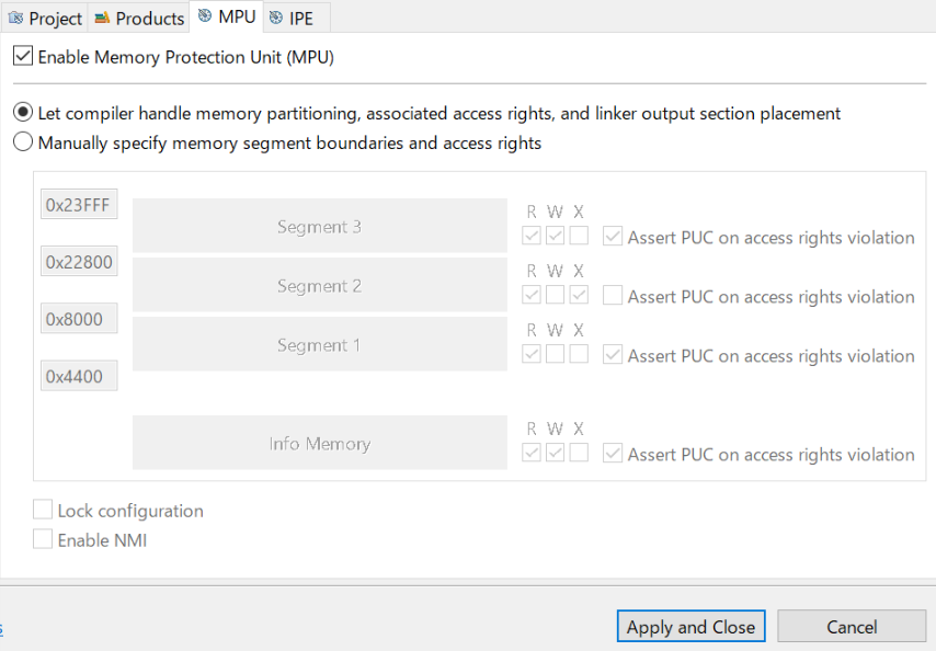
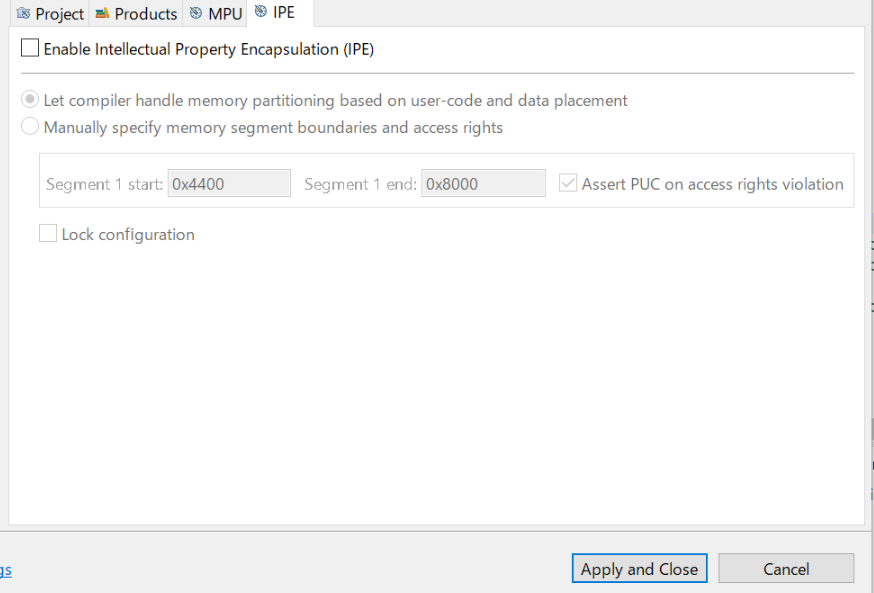
The error addresses are different by board, but the addresses are all inside MPU protected area.

Board#40:
[2019/5/28 13:45:43] [ERROR] MSP430: File Loader: Verification failed: Values at address 0x0D558 do not match Please verify target memory and memory map.

Board#24:
[2019/5/28 13:57:33] [ERROR] MSP430: File Loader: Verification failed: Values at address 0x0D7EC do not match Please verify target memory and memory map.

Board#42:
[2019/5/28 13:39:08] [ERROR] MSP430: File Loader: Verification failed: Values at address 0x0D7F6 do not match Please verify target memory and memory map.

Board#63:
[2019/5/28 13:51:44] [ERROR] MSP430: File Loader: Verification failed: Values at address 0x0C832 do not match Please verify target memory and memory map.

Board#22:
[2019/5/28 14:15:09] [ERROR] MSP430: File Loader: Verification failed: Values at address 0x0AE34 do not match Please verify target memory and memory map.

With the same board, always the same address is failed. For example, Board#40 always fails at 0x0D558.
Is this related to MPU function? There are many other boards which are not failing with exactly the same procedure.
Any possible cause of such issue?

Thanks and regards,
Koichiro Tashiro

  • Hi

    I'm working with thread owner.

    I got debug server log generated by Uniflash when verification error occurs.

    (Path of execution file is deleted because it contained customer info.)

    no40.zip

    Please refer it if it help.

    BestRegards

  • Hello,

    Judging by your test procedure, it seems to be that something might be overwriting the memory at these specific locations either during the functional tests or during the power cycle.

    Do you still see this phenomena if you just program the board, power cycle it, and then verify that same program?

    Best regards,

    Matt
  • Hi Matt

    Thank you for your reply.

    The customer checked following procedure 10 times with Board #40.

    1) Write program with Uniflash
    2) Verification is OK
    3) Power cycle the device (power-off, then power-up again).
    4) Verify again with Uniflah => Verification fails
    5) Erase

    In procedure above, they got same error message on Uniflash console but the address was changed.
    It means "0x0D558" in error message changed to other value.

    BestRegards

  • Thank you for confirming that step. Steps to narrow down the problem can take multiple paths due to the multiple variables we are working with (i.e. custom board, custom software, Uniflash version, etc. )

    Just to clarify, what version of Uniflash is your customer using?

    I downloaded the latest version and tried recreating your test setup on an MSP430FR6989 launchpad and an example code from the TI Resource Explorer and am unable to see a verification failure, even after multiple power cycles. Could your customer try uploading a TI provided example code for the MSP430FR6879 from the TI Resource Explorer and trying the test again? If the verification failures go away with the example code then it would start to point us in the direction of the custom software.

    Best regards,

    Matt

  • Hi Matt

    Thank you for your reply.

    I can answer the following question at this time.
    >Just to clarify, what version of Uniflash is your customer using?
    Uniflash is v4.5.0.

    BestRegards
  • Good to know! First off, I would recommend upgrading to the latest version ( Uniflash 5.0 ) and confirming that the phenomena is still occurring. If so then we can continue the initial debug steps I recommended in the previous comment.

    Best regards,

    Matt
  • Hi Matt

    Thank you for your reply.

    We tried Uniflash5.0 but could not see improvement.

    By the way, our project uses MPU function.

    Could you please see our configuration?
    I attach CCS settings and snippet of source code.

    - CCS settings

    -Source code snippet

    --------------

    void main(void)

    {

       WDT_A_hold(WDT_A_BASE);     // WDT stop

       // Setting segment

       MPUCTL0_H =0xA5;                // Write PWD to access MPU registers

       MPUCTL0 = MPUPW;                // Write PWD to access MPU registers

       MPUSEGB1 = 0x0800;              // B1 = 0x0800; B2 = 0x2280

       MPUSEGB2 = 0x2280;              // Borders are assigned to segments

       MPUSAM = MPUSEG1RE |/* MPUSEG1WE |*/ MPUSEG1XE |        // Segment 1 - Execute, Read

                MPUSEG2RE |/* MPUSEG2WE |   MPUSEG2XE | */     // Segment 2 - Execute, Read, write

                MPUSEG3RE |/* MPUSEG3WE |   MPUSEG3XE | */     // Segment 3 -          Read, write

                MPUSEGIRE  /*|MPUSEGIWE                 */;    // Info      - Execute, Read

       MPUCTL0 = MPUPW | MPUENA | MPUSEGIE;        // Enable MPU protection

    ***

    --------------

    Did you see any issue on this MPU configuration?

    BestRegards

  • Hello,

    As an initial pass through of the source code for enabling the MPU, I noticed that the comments are different from what is actually happening.

    The MPUSAM register is being initialized so that:
    Segment 1 ( 0x4400 - 0x7FFF ) is Read and Execute
    Segment 2 ( 0x8000 - 0x227FF) is Read only
    Segment 3 ( 0x22800 - 23FFF) is Read only
    Info is Read only

    The comments are describing the segments to have different access rights than what is currently implemented.

    Another thing I noticed is that the line "MPUCTL0_H =0xA5;" is not needed, the only thing you need to do to access the MPU registers is the line of code right under it: MPUCTL0 = MPUPW;

    Has the customer been able to confirm similar behavior (unexpected verification failure) with TI Provided example code on their currently failing custom boards? If they are unable to recreate the behavior with the TI Example code then it would lead me to believe that some aspect of the source code is causing the verification failure.

    Best regards,

    Matt
  • Hi Matt

    Thank you for your reply.

    >Another thing I noticed is that the line "MPUCTL0_H =0xA5;" is not needed,
    Regarding to MPU settings, I understand MPUCTL0_H=0xA5 is not needed.
    While at the same time, I can regard MPUCTL0_H=0xA5 does not have impact for our settings, is it okay?

    I downloaded and verified a project generated as new project only with main() .
    The error was not replicated. There is possibility the error is caused of source code.

    I will have to check customer project including linker and property settings.
    Regarding to aspect of linker or project property, please tell me if you have any idea where to review.

    BestRegards
  • The write to MPUCTL0_H should be okay; a wrong access to the MPUCTL0_H register will disable write access to the MPU module so if you are able to see that the MPU peripheral registers are properly being initialized then it is fine.

    It may be best to focus on areas of the project that deal with or affect the memory during run-time. Perhaps you can begin to remove blocks of the source code until you are able to identify which block has a hand in causing the verification failure after a power cycle.


    Regarding the linker file and project properties, has the customer made any major modifications to the default settings?

    Best regards,

    Matt
  • Hi Matt

    Thank you for your reply.

    I used the customer's project with blank source code, that is all functional code is commented out,
    then the verify error was replicated.

    On the other hand, making new project and adding customer's functional code into it,
    then the verify error was not replicated.

    >Regarding the linker file and project properties, has the customer made any major modifications to the default settings?
    Yes. They seems to use modified linker command file from default. (Memory map and interrupt vectors)

    I might take a little time to investigating and reply.
    I apologize for inconvenience.

    BestRegards

  • Now that is some rather interesting findings!

    Don't worry about the additional time needed to investigate, that is all part of the fun of debugging :)

    If you were able to resolve the issue using default project settings, TI provided linker file, and the customer's functional source code, wouldn't this be a viable starting place to develop the final solution from? The functionality would have to be tested for proper operation and minor tweaks may need to be made based on the customer's requirements but starting from a known working software solution is a good place to be at.

    Best regards,

    Matt

  • Hello,

    It's been a couple days since hearing back so I am going to go ahead and mark this thread as "TI Thinks Resolved" for now.

    From our previous correspondence it seems pretty valid that some modification made to the linker file and/or project settings caused the verification failure because porting all of the project's functionality to a new project fixed the issue. If this thread locks and there is more details to the story feel free to open another post linking this one.

    Best regards,

    Matt

**Attention** This is a public forum