This thread has been locked.

If you have a related question, please click the "Ask a related question" button in the top right corner. The newly created question will be automatically linked to this question.

CCS/EVM430-FR6047: Volume Flow rate Fluctuation

Part Number: EVM430-FR6047

Tool/software: Code Composer Studio

Hi,

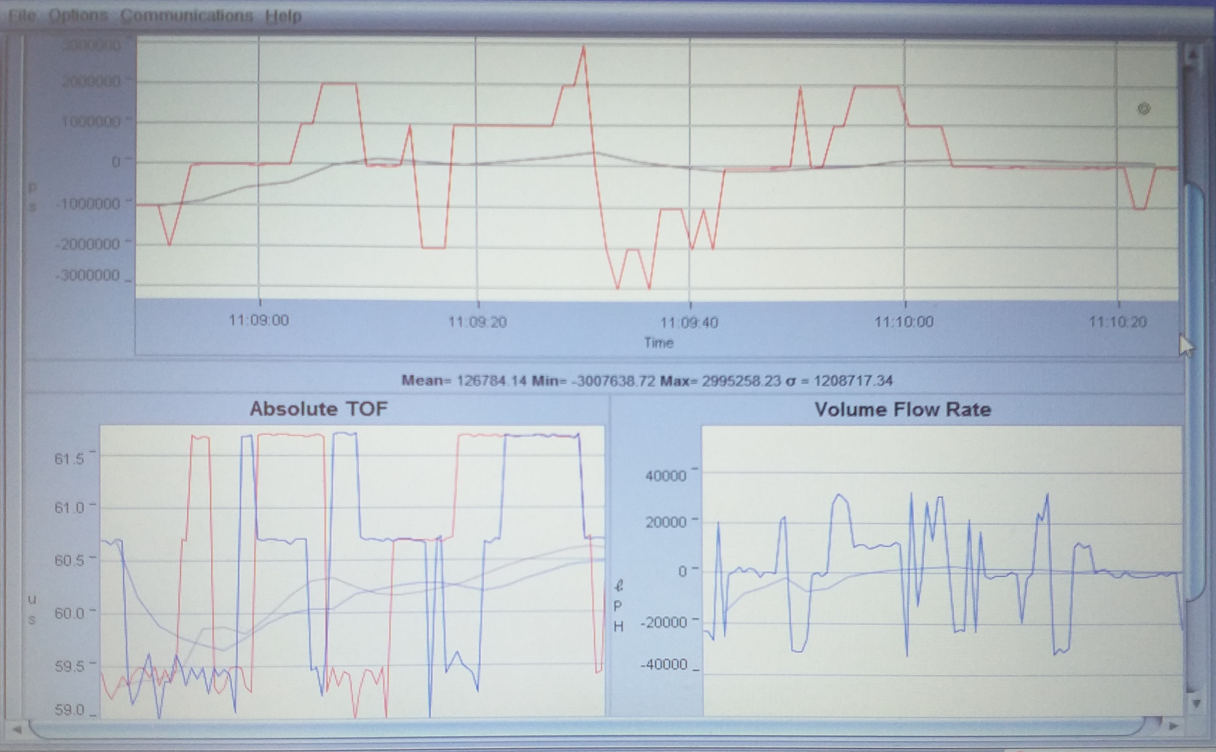
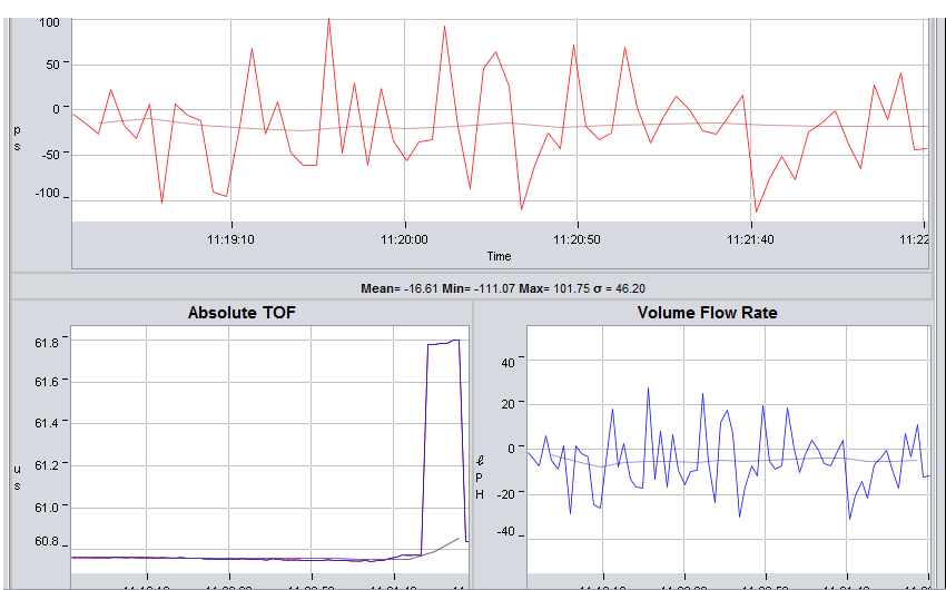
While we were testing,volume flow rate was swinging abnormally between negative (about -3.5 KLPH) to 2.3 KLPH.

Transducer connection was verified and configuration parameters are default.

What could be the issue?

Regards,

Divya Harikumar

  • Divya,

    Some variation is expected and should be averaged, but this seems large.

    What is your reference flow rate in these tests?

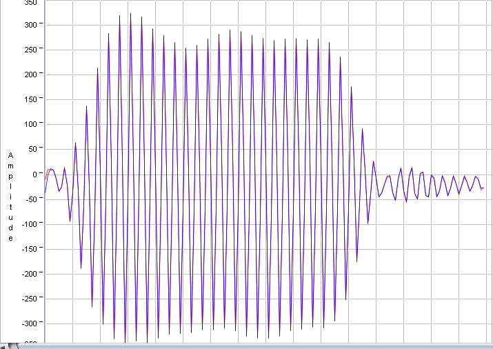
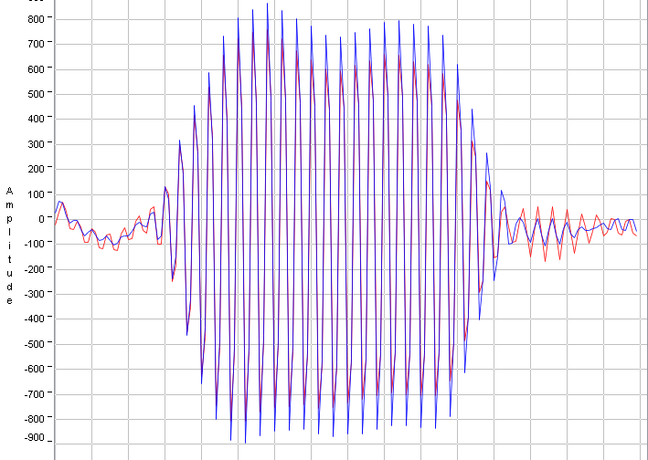
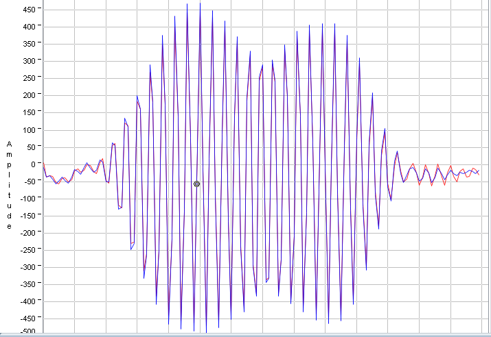
    Can you provide a screen shot of your ADC capture at zero flow? What is the level of ADC counts? For a 1MHz pipe, it should be less than 1000. Around 900 is a good target. If it is high or low, you may need to adjust the gain setting.
  • Eddie,

    We had tested for both low(below 100LPH) and high flow rate(400 LPH and above) and found abnormal variation.

                                                            ZeroFlow ADC capture

    Currently ADC count (ns) is set to a higher value for a 1 MHz transducer pipe.

    Are you suggesting that ADC count (ns) for a 1 MHz pipe must be set to around 900 in GUI?

    Regards,

    Divya Harikumar
  • Divya,

    I am actually referencing the number of ADC counts that you are seeing in your zero flow ADC capture.  You should increase the gain to get this signal to around +/-900 counts.  Sorry for not being more clear on that.  This higher signal level should help with the drift performance you are seeing.  Let me know if that helps. 

  • Divya,

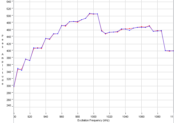
    You may also want to run a frequency sweep on your pipe to find the ideal resonant frequency. You can do this by setting the start frequency(f1) on the configuration tab(I recommend 900kHz) and then setting the step size and number of captures on the frequency sweep tab. I recommend using step size of 5kHz and increase the captures until the end frequency is 1100kHz. You want to use the frequency with the largest amplitude. Once this is determined, set your f1 frequency to this and capture waveforms again. This should all be done with zero flow in the pipe.
  • Eddie,

    I increased the gain to 9 db and capture duration to 80 us. I reduced ups0 to ups1 gap to 500ms and set adc count to 25000 ns.

    Just wanted to know if the above ADC waveform and variations in VFR are expected for zero flow rate?

    Best regards,

    Divya Harikumar

  • Divya,

    The variations are greatly improved from what you showed earlier, but still higher than expected.  A really good pipe design should be getting +/-1LPH swings or less.  Are you using an off the shelf pipe such as Audiowell possibly?  

    Couple of notes:

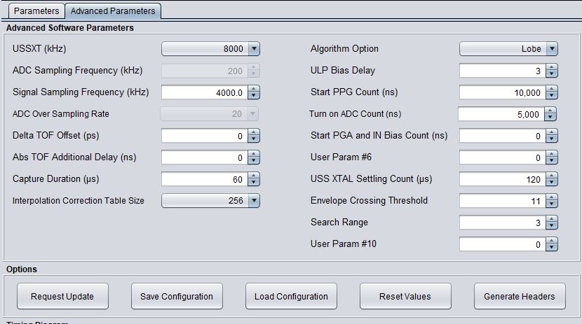
    Change set ADC count back to 5,000.  For a pipe with greater than 30uS gap, I do recommend leaving the ULP Bias Delay, Start PPG Count, Turn On ADC Count, and Start PGA and IN Bias Count to default values as shown below.  

    Check the resonant frequency of your pipe using the frequency sweep tab.  Your ADC waveform doesn't look very smooth and could be improved by finding the peak resonant frequency.  If you do find that there is a better frequency to use, recheck your ADC capture and adjust the gain again to get back to around +/-900.

    You could probably reduce the capture duration as you are capturing a lot more than the necessary signal.  Maybe around 60uS.

    You could decrease the gap between pulse start and ADC capture to center your ADC capture a bit better.  Maybe reduce by about 2-3uS. 

  • Eddie,

    We are using a pipe similar to audiowell. 

    By off shelf pipe do u mean the pipe assembly or the transducer pipe?

    The frequency sweep under no flow condition is attached.

    I did change back all the values to default and then set capture duration to 60us as you suggested,but the swing still seems to exist.

    Best Regards,

    Divya Harikumar
  • Divya,

    By off the shelf, I just mean something that is widely available, like the DN20/25 pipes with transducers available from audiowell.  

    You should also reduce the gap by a few microseconds so there is a more clear transition to the signal.  

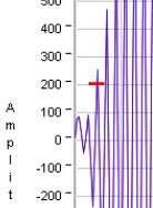
    Looking at your ADC signal again, I think that the envelope crossing threshold could be improved as well.  You want to lock onto the first lobe which looks to have a crossing around 200.  See image below with red marking.  In advanced parameters, you could change the envelope crossing threshold to 20.  With the default setting of 11, it is possible the first part of the signal could get locked with fluctuations throwing the measurements off.  

  • Eddie,

    I increased the gain to 6 db,capture duration to 60 us and no.of pulses to 30.

    I reduced ups0 to ups1 gap to 500ms and gap between pulse start and adc capture to 57us.

    Just wanted to know if the above ADC waveform and variations in VFR are expected for zero flow rate?

    Best regards,

    Divya Harikumar

  • Divya,

    This looks really good for the most part!  The only suggestion I would make is that you can probably reduce the number of pulses as you really only need to see one peak in the ADC waveform.  For your pipe, probably around 20 pulses is good.  The signal you have now is not really a problem, but will be a higher current consumption.  You should be able to reduce to 20 or 25 pulses and see the same VFR performance with lower current consumption.  The variation you see in VFR at zero flow looks similar to what we see on good quality pipes.  Nice work!

  • Hi,

    I reduced the no.of pulses to 20 as you suggested.

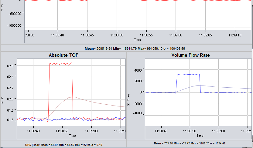
    While performing flow test for a constant flow,a sudden peak(2000 LPH) was observed in VFR after which had settled to a constant flow(50LPH).

    What could have been the reason for such a sudden spike?

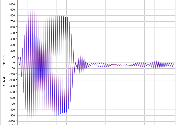
    I have attached the ADC waveform that i obtained during flow test.

    Regards,

    Divya Harikumar

  • Divya,

    This could be the setting of the threshold level since it looks like your peak amplitude has decreased with less pulses(this is expected).  Boost your gain to get the signal back to 900 to 1000 ADC counts and test again.  Let me know if you still see such an issue.

  • Eddie,

    Are you suggesting that even during flow test the ADC peak amplitude must lie between 900-1000 counts?

    Best regards,

    Divya Harikumar

  • Divya,

    Generally, this is recommended.  You can do this by using the AGC(automatic gain control).  This is available in the demo application code, but default is off.  The FAQ discusses how to enable this and what configuration to use for 1MHz and 2MHz transducers.  See #3 on page 11. 

    http://www.ti.com/lit/an/slaa837a/slaa837a.pdf 

  • Eddie,

    I did enable AGC in the same way as specified in the document.

    ADC waveform seems to have decreased in amplitude than before during runtime.

    The unusual peak still exists and in fact increased over time

    Such behavior was started to be seen when i migrated to the newer USS code,

    Best Regards,

    Divya Harikumar

  • Divya,

    When you enable the AGC, are you also setting the interval?  In USS_App_userConfig.h, set the interval to some value other than 0.  This defines how often the AGC calibration routine occurs.  For example, 1 means calibrate every time a measurement is made, 5, every 5th measurement, etc.  

    #define USS_APP_AGC_CALIBRATE_INTERVAL              (0)

**Attention** This is a public forum