This thread has been locked.

If you have a related question, please click the "Ask a related question" button in the top right corner. The newly created question will be automatically linked to this question.

MSP430FR2311: MSP430FR2311 P.W.M

Part Number: MSP430FR2311


hi all...

I am working with  MSP430FR2311 , VCC is 3.3V.

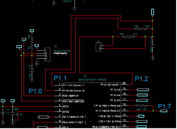
i am using Timer B0.2 as  PWM  and use  P1.7  for PWM output.

So far everything works fine and  I can control PWM.

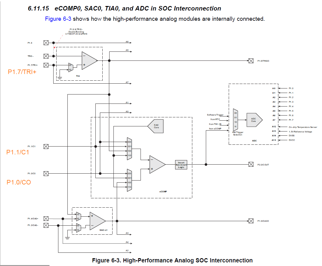
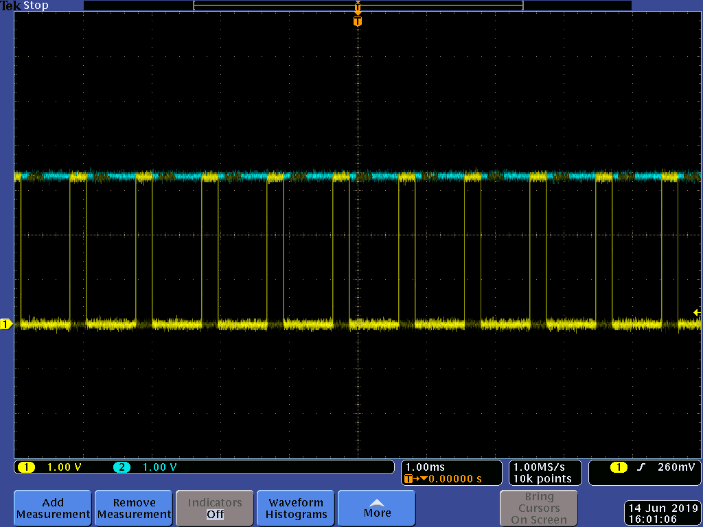
Something very strange that I never saw,..... When I use P1.1 high on the seam time while PWM working

the voltage of  P1.7  PWM output  falls  from 3.3V to 1V.

It looks like someone is loading but I do not understand what...

I'm also a hardware man and I still can not understand what's going on here...

please help...

Aharon.

  • Please see below pic of the signals.

  • Hello Aharon,

    How (what instruction to you use) to set or clear P1.1?
  • hi Dennis ,

    i am using  P1.1 as input or output.

    here i define the port:

    #define R_Ref_OUT            P1DIR |=  BIT1;        // P1.1  as Out
    #define R_Ref_out_ON       P1OUT |=  BIT1;        // P1.1   Reference Resistor  I/O ON
    #define R_Ref_out_OFF     P1OUT &= ~BIT1;        // P1.1   Reference Resistor  I/O OFF
    #define R_Ref_IN               P1DIR &= ~BIT1;        // P1.1  as In
    

    and here i use it:


       R_Ref_OUT;  
      R_Ref_out_ON ; //    <<<<<PWM out go to 1V is happen here
      
       for(Counter_Time = 0;Counter_Time < 10000; Counter_Time++);
       
       R_Sens_IN;
       R_Ref_out_OFF;

    Thanks
    Aharon

  • Hi Aharon,

    Not sure what is happening. Checked for errata and found nothing.
    If you don't enable the PWM output, does the P1.7 toggle when you set/clr P1.1?
    What are your P1SEL settings for that port?
    Is there anything connected to P1.7?
  • hi

    After many hours of research without result.
    now i understand that the whole picture is missing and I will spread what I know with hope for help.
    I work with these parts: 

    1. eCOMP0

    2.Timer B0.2 as  PWM  and output on P1.7

    3. P1.0 as input for V+ terminal , DAC as input for V- terminal

    4. P1.1 ,P1.2  as input/output

    5. VCC = 3.3V

    while PWM   (on P1.7 ) working and eCOMP0 is OFF i can use P1.1 ,P1.2 NORMAL and PWM voltage level is 3.3V.

    while PWM   (on P1.7 ) working and  eCOMP0 is ON  if P1.1  or  ,P1.2   ON  PWM ( on P1.7 ) voltage level is 1V.

    There seems to be a connection between Timers and eCOMP0  and you can not work with them together.

    here i set the  eCOMP :

    //---------------------- Setup eCOMP ------------------------------
     
      TRI0CTL |= TRIPSEL1 | TRIPSEL0;
      P1SEL0 |= BIT0;                                 // Select eCOMP input function on P1.0 /C0
      P1SEL1 |= BIT0;
     
      CPCTL0 &= ~CPPSEL0;                  // Select C0 on P1.0 as input for V+ terminal
      CPCTL0 |= CPNSEL1 | CPNSEL2;         // Select DAC as input for V- terminal
      CPCTL0 &= ~CPNSEL0;
      CPCTL0 |= CPPEN | CPNEN;             // Enable eCOMP input
      CPCTL1 |= CPIIE ; 
      CPDACCTL |= CPDACEN;                // Select VCC as reference and enable DAC
      CPDACDATA |= 10;                    // CPDACBUF1 = 10/64 * 3.3V = 0.515V as reference
      CPCTL1 |= CPEN | CPMSEL ;                           // Turn on eCOMP, in high speed mode
      CPINT &= ~CPIFG;                   // Clear Interrupt flag 
      CPINT &= ~CPIIFG;                  // Clear Interrupt flag 


     //------------------------------------------------------------------------    

    here the PWM  functions 

    void PWM_ON(unsigned int DC)
    {
        TB0CTL = MC_0;
        TB0CCR0 = 31250-1;                        // PWM Period 1.5MHZ timer input
        TB0CCTL2 = OUTMOD_3;                      // CCR2 reset/set
        TB0CCR2 = DC;                            // CCR2 PWM duty cycle
        TB0CTL = TBSSEL__SMCLK | MC__UP  | TBCLR;  // SMCLK, up mode, clear TBR
      
    }                              


    void PWM_OFF(void)
    {
     
      TB0CCTL2 = OUTMOD_0;                      // PWM_OF  CCR1 reset/set
      TB0CTL = TBSSEL_2 + MC_0 + TBCLR;        //PWM_OF
     
    }

    here i use the  P1.1 ,P1.2 that lead to PWM out to be 1V instead 3.3V

     //------------Chargeing
       
       R_Sens_OUT;
       R_Ref_OUT;  
       R_Sens_out_ON;  // >>>>  PWM go to 1V
       R_Ref_out_ON ;  // >>>>  PWM go to 1V
      
       for(Counter_Time = 0;Counter_Time < 10000; Counter_Time++);
       
       R_Sens_IN;
       R_Ref_out_OFF;
       

    I hope it's clearer now. At the moment, my conclusion is that it is impossible to operate PWM and  eCOMP at seam time


    And I do not know why....

    Thanks

    Aharon


  • Aharon,

    In an effort to try to understand better your application, is there anything connected to P1.1?  I noticed comment about reference resistor.  I was wandering if you are using a voltage divider powered by P1.1 output and the the divider output is connected to P1.0 (v+ on the comparator).

    Also, regarding setting the following register bits, what is your intended purpose for your application?

    TRI0CTL |= TRIPSEL1 | TRIPSEL0;

    According to the datasheet, the configuration you chose is not used.

  • hi Dennis ,

    Many thanks.

    regarding P1.1 , P1.0 ,P1.2  i am implementing  slope A2D   with comperator to calculate NTC Temperature resistor like

    Application Report  SLAA129B .

    .its a well known TI application. I used it many times  with PWM with a many TI processors and here  on MSP430FR2311  I got into trouble and cant implant  comperator  slope A2D   with  PWM.

    here you can see this part on my scheme:

    regarding :TRI0CTL |= TRIPSEL1 | TRIPSEL0; 

    I saw that there might be a connection to TIA  module and while trying  to find a solution I thought to disconnect P1.7 from TIA.

    Of course it did not help,,,

    Thanks

    Aharon.

  • Hi Aharon,

    I have reached out to one of experts for these peripherals on this device.
  • hi Dennis ,

    thanks i will wait for your update.

    do you need any more information or code?

    Aharon.

  • Hi Aharon,

    Is it possible for you to share all of your code? I'd like to run it on a FR2311 launchpad and see if I can replicate the issue.

    Thanks,

    Mitch
  • hi Mitch

    yes i can... but how you can use it?? FR2311 launchpad  is  without the peripherals i have on my board?

    Maybe you want to build something  around   FR2311 launchpad ?

      Thanks

     Aharon.

  • Hey Aharon,

    Just wanted to let you know I am still working on this and will provide an update soon.

    Thanks,

    Mitch

  • hi Mitch,

    thanks.

    I'm really stuck with it.
    You still want my  full code ?

    Aharon.

  • Hey Aharon,

    Sorry for the delay. I have some updates that hopefully resolve this issue:

    I initially tried a very basic test of outputting a PWM on P1.7 (like you do in your SW) and running the eCOMP module with your settings. I saw a very similar, but different problem. When eCOMP is enabled, my PWM signal fell flat to 0V (as opposed to yours falling to 1V). When I disabled eCOMP, the PWM came back to life with no issue. Even though I didn't see the exact same problem as you, I saw very similar behavior. 

    After looking around in our documentation, I came across the following:

    TB0TRGSEL is 0 by default - meaning that the eCOMP output can set the P1.7 timer output to high impedance. 

    I set the TB0TRGSEL bit to 1, and I saw my PWM functioning normally with the eCOMP module was enabled. I think what we were both observing was the eCOMP module setting the PWM pin to a high-impedance state.

    Below is the SW I tested that gave me a functional PWM signal on P1.7 with eCOMP enabled (with your settings) and P1.1 driven high:

    #include <msp430.h>
    
    int main(void)
    {
        WDTCTL = WDTPW | WDTHOLD;            // Stop WDT
    
        P1SEL1 |= BIT7;                      // P1.7 options select - TB0.2 output
        P1SEL1 |= BIT2;                      // TB0TRG Trigger
        P1DIR |= BIT1 | BIT7;                // P1.1 and P1.7 output
    
        P1SEL0 |= BIT0;                      // Select eCOMP input function on P1.0 /C0
        P1SEL1 |= BIT0;
    
        P1OUT |= BIT1;                       // Drive P1.1 high
    
        // Disable the GPIO power-on default high-impedance mode to activate
        // previously configured port settings
        PM5CTL0 &= ~LOCKLPM5;
    
        SYSCFG2 |= TB0TRGSEL__EXTERNAL;       //Change TB0 high-impedance trigger to external (P1.2)
    
     //Customer eComp Settings
         CPCTL0 &= ~CPPSEL0;                  // Select C0 on P1.0 as input for V+ terminal
         CPCTL0 |= CPNSEL1 | CPNSEL2;         // Select DAC as input for V- terminal
         CPCTL0 &= ~CPNSEL0;
         CPCTL0 |= CPPEN | CPNEN;             // Enable eCOMP input
         CPCTL1 |= CPIIE ;
         CPDACCTL |= CPDACEN;                // Select VCC as reference and enable DAC
         CPDACDATA |= 10;                    // CPDACBUF1 = 10/64 * 3.3V = 0.515V as reference
         CPCTL1 |= CPEN | CPMSEL ;                           // Turn on eCOMP, in high speed mode
         CPINT &= ~CPIFG;                   // Clear Interrupt flag
         CPINT &= ~CPIIFG;                  // Clear Interrupt flag
    
    // Configure T0.2
        TB0CCR0 = 1000-1;                         // PWM Period
        TB0CCTL2 = OUTMOD_7;                      // CCR2 reset/set
        TB0CCR2 = 250;                            // CCR2 PWM duty cycle
        TB0CTL = TBSSEL__SMCLK | MC__UP | TBCLR;  // SMCLK, up mode, clear TBR
    
    
        __bis_SR_register(LPM0_bits);             // Enter LPM0
        __no_operation();                         // For debugger
    }
    

    Here is also a screenshot of my oscope measurements of the above SW. You can see the PWM signal is functioning at 3.3V (yellow) with P1.1 driven high (blue). eCOMP is also enabled with your settings:

    I think that if you include the SYSCFG2 |= TB0TRGSEL__EXTERNAL; line you will see normal PWM behavior (eCOMP will no longer be a high-impedance trigger source). Do not set the P1.2 function to TB0TRG. Since you are changing the timer high impedance source externally to P1.2, this could cause accidental high-impedance triggers. I configured P1.2 as TB0TRG in my SW for debug purposes only.

    Please let me know if this works!

    Thanks,

    Mitch


  • Hi Mitch.

    first i will say it work ,  just add  this SYSCFG2 |= TB0TRGSEL__EXTERNAL.

    After you have given a solution I also looked for ... and found the place that explains it more clearly


    I do not know how long you've devoted to it.  I gave it ... two whole days and I gave up.
    I have to say that it could have been written more user-friendly and thus prevent all the time lost.
    I am very grateful to you for all the effort invested in helping a stuck client.

    Thanks

    Aharon.

  • Hi Aharon,

    I'm glad we were able to find the source of the issue! I apologize for the inconvenience and frustration. I hope the rest of your development goes smoothly.

    Thanks,

    Mitch

**Attention** This is a public forum