This thread has been locked.

If you have a related question, please click the "Ask a related question" button in the top right corner. The newly created question will be automatically linked to this question.

MSP430FR2633: can not select captivate slider pins correctly in design center

Part Number: MSP430FR2633
Other Parts Discussed in Thread: CAPTIVATE-PHONE

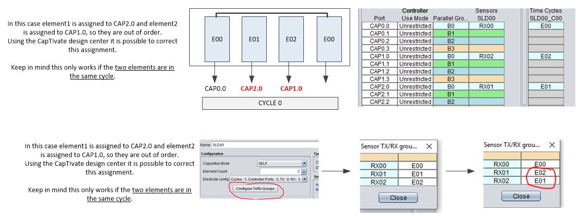
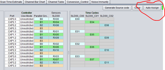
I selected the corresponding pins for my sliderlayout but the program has a different order. I am very confused?
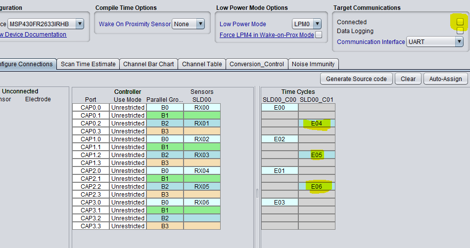
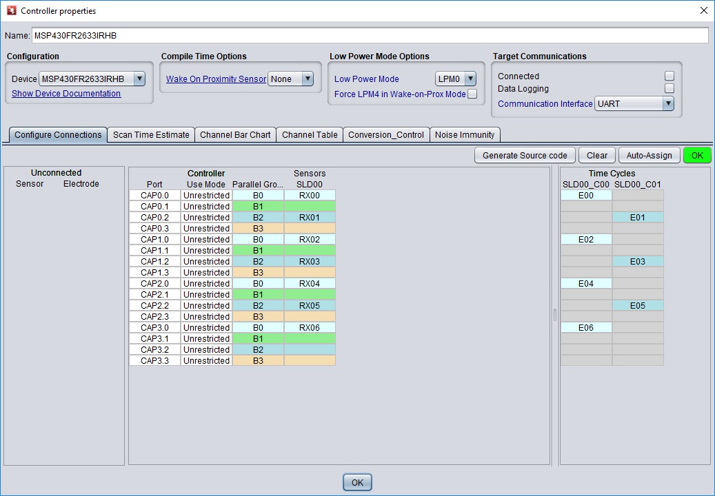
In configure connections I have selected which electrode of my Slider is connected to which pin(see picture)

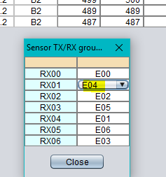
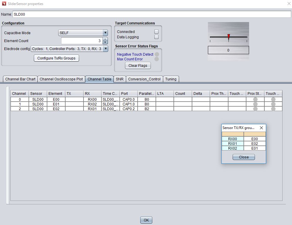
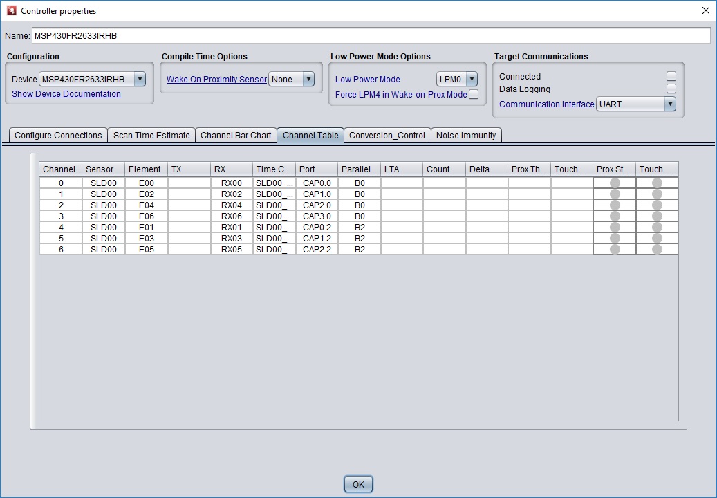
But the Slider uses a different order seen in the Channel table( see picture 2)

  • Hallo 6058396

    can you send me a screenshot of the slider layout and the order of the order of pins you like to have?

    Thanks

    Regards
    Kostas
  • I want to have

    cap 0.0 for the first element

    Cap 0.2 for second

    Cap 1.0 for third

    Cap 1.2 for 4

    Cap 2.0 for 5

    Cap 2.2 for 6

    Cap 3.0 for 7  (unsure because it should be connected to first element)

    And that is how I have selected the electrodes in the configure tab. But it surprisingly uses a different scan order for the slider so the value jumps around a lot if I try to use it?

    Just to clarify It uses the order which is listed in the channel table from top to bottom and not like I wanted it to be. That’s why I added both pictures.

  • Any hints regarding this topic? I cant get it working...
    Whats the problem?

  • Hallo Florian,

    thanks for the information and your observation on this specific topic for sliders with more than 4 elements.

    You are right, we do not have information covering this part of the technology. We are working on that.

    This is a very seldom request, as most of the applications can be served with up to 4 electrodes. Even a 30cm slider.

    In case you don't have done already, please check the Captivate technology guide for some basics implementation on sliders.

    Some basic explanation.

    For sliders with up to 4 electrodes you can see our recommendations in the technology guide. Depending on the device if the right pin assignment is done the electrodes are scanned in one cycle in parallel.

    For sliders with more than 4 electrodes we would need a second time cycle SDL00_C01 in your project.

    The software library processes the measurements in the following order: element1, element2,element3….element6, in order to determine a position correctly.

    In your project the assigned and process order is element0, element2, element4,element6,element1,element3 and element5.

    We need to change the order to comply with the software as you can see in the screenshot below.

    This can be done in the CDC.

    - Uncheck connection  box

    - press "Configure TX/RX Groups"

    - click on the "E01" drop down menu and change to the RX01--> E04

    - Same for the RX03--> E05 and RX05-->E06

    - Generate Source code

    - Program the device

    I hope this will solve the problem.

    Regarding the use of the CAP3.0. If that is the last element of the sensor ( half) you need to connect it directly to the first element of the sensor.

    Please let me know if that solves your issue with the slider.

    Best regards

    Kostas

  • Sorry, I have seen that the pics are missing in the previous response

    Regards

    Kostas

  • thats unneccessary complicated in my eyes and dont works I simply want to select which pin is connected to which sensor element, but it dont works. Intuitive would be RX0 is element 0 and sensorpad 0 from the slider and RX1 is element1 and Sensorpad1 from the slider.....

    thats not only a problem with the extended number of elements!  its simply not possible to use the pins I want to use for the captivate slider function in a reasonable way.  I have also a 4 element slider here, which has the same layout like you recommend. I want to use Cap 0.0for the first sensor element , cap 0.2 for the second sensor element, and cap 1.0 for the third sensor element. I cant get it to work!

    I tried your suggested method with configure RX/TX groups, the resulting scan order seems to be the same.


    In which file from the generated source are these RX/E/Pin mappings? In which order are the things scanned?

  • The problem here is you can't use the pins in the order you are specifying.

    For the slider algorithm to work properly, each electrode must be connected to a pin on a separate block (see illustration below).

    Note the assignment order - E00 -> CAP0.x,  E01 -> CAP1.x,  E02 -> CAP2.x, etc.

    In your configuration, element 1 is out of order in terms how the channels are scanned.  You scan order becomes E00, E02, E01 and won't work.

    Now, there is a way in the design center to switch electrode assignments but this only works if the two pins are in the same measurement cycle.

    Is there any reason why you cannot assign each electrode to a separate block?

  • Thanks for the explanation, i have spent a lot of time getting this to work without any progress.
    I have nowhere read about these topics before in the design guide and all other documents I have read!

    Nowhere is written that the maximum number of sliderelements is 4! also you said in above posts that it is possible! I also couldnt find info that each element has to use a separate block.

    The reason is I have already a few different slider layouts made which now can`t  be used. 


    You should update the documentation and also build in a warning in the design guide that this does not work!

  • I apologize for the trouble.  Yes, I agree the documentation is not explicit in describing this level of detail and I will add this information in the design guide chapter for slider and wheels. I do want to point out the chapter that discusses the Captivate GUI controls in the design guide.  Look for the sub-section titled "Configure TX/RX grouping".  There is a description of a slider implementation.

    Allow me to clarify that you are not limited to only 4 electrodes.  The library supports up to 12 elements and describes this in the Captivate design guide chapter under the slider and wheel section.

    Ordinarily, when creating the slider design in the Captivate design center, you want the design center to determine these connections.  Not only will this be correct but will also choose the optimal connections in terms of parallel scanning based on your sensor type and number of electrodes.  This is done using the "Auto Assign" button.

    Here is example of 12-element slider that was created using the auto-assign.

    Notice that starting with time cycle SLD00_C00 the elements are in increasing order E00, E01, E02, E03, (moving from block 0 to block 1 to block 2 and then block 3)  then in the next time cycle they continue with E04, E05...

    Also notice that this is most efficient because it is possible to scan all 12 electrodes in only 3 time cycles.

    Now, I understand that your required PCB layout may not match the specific combination of connections between the MCU and the slider electrodes created by the design center.  Is there a reason why you didn't use this feature and chose the specific pins that you did?  I ask so I can better understand your application.

  • I simply didin´t know that you can´t use whhatever pins I like. I configured it like I did in the designprocess, no errors came up. The auto assign gave me "weird" connections which looked just "random" because i didnt knew how this works until this thread. I never read anywhere that it is a must to use the auto assign feature.
    On other touchplatforms like the cypress PSoCs its a lot more intuitive and easier.

    Thanks for the help I was able to configure it to scan in the correct order.

    Is there any shield function avaialable in the captivate universe? Like a hatched pattern arround electrodes to improve Performance and give Water resistance?

  • Let me clarify your comment.  You are not "required" to use the auto assign.  This feature is there to take all the guess work out of selecting the appropriate connections and make the design process streamlined.  The reason for selecting pins in a certain order for sliders and wheels is a limitation of the slider and wheel software algorithms, not the hardware.  You are totally welcome to choose any pin you like and write your own slider driver :)

    I have taken an action item to add some clarity to our documentation to prevent this confusion in the future.

    Now regarding the shield function, the CapTIvate hardware does not directly provide a "drive-shield" pin, however, there are couple of ways design a layout that will provide immunity to moisture.  Here is a link to video showing the performance that can be achieved. Here is a link to the reference design.

    1. You can create a "hatched" area, let's call it a guard channel, around the self capacitive slider electrodes and connect this area to an available Captivate IO pin and configure it in the design center as either a self capacitive button or proximity sensor.  How this works is if water is present across both your slider elements and the guard, both will detect the moisture and software can ignore the inputs until the condition is cleared.

    2. Another option is to use "mutual capacitive" mode.  It's behavior when water is present is different compared to self capacitive mode such that it causes a negative shift in the baseline measurement when water is present and this can be used to know when water is present.  You would have the same electrodes for your slider, but make the slider mutual, not self capacitive.  You can do this by keeping the electrodes the same RX connections and make the hatched area surrounding these electrodes the single "TX" connection.  BTW, this is how it is done in the video above.

  • With solution 1, how can I assure that there is always "shield" signal on this hatch when I simply connect a button to it ? I thought the captivate elements are not scanned simultanously? Do i need to assign the same block or another block? What if I use 2 blocks for the slider do i need to make two pins of both blocks connected to one "shield"?

  • Yes - you are creating a button (guard electrode).  No - the elements are measured simultaneously (E00..E03) in one time (cycle 0).

    I want to make sure I understand this application so I can point you in optimal direction.  This is slider that will be exposed to moisture?

  • But if i use a slider with more than 4 elements, it needs to be splitted in two time cycles....thats why I am asking...
    do i then need to connect two buttons one out of each time cycle to the shield electrode?

    I want to test the slider abilities, moisture insensitivy would be nice, still working while wet would be perfect.

  • Ordinarily I would not recommend to connect two pins (one from a separate block) to the same electrode shield, as the inactive pin effectively shorts the other to GND while the other is attempting to drive the shield.  However, you can change the default "off" state of any CAPT IO pin from GND to HI-Z in the Captivate design center (it is the idle state in the sensor conversion control tab).  I'm not recommending this, as I have never attempted to do this, but it is something you can experiment to see if it will do the job for you.

    The problem with driving a shield with another CAPT IO pin is that pin must be driven in the same measurement cycle as the CAPT IO pins connected to the slider elements.  With only 4 blocks you are limited to a 3-element slider, which still won't work because the shield pin is essentially a different sensor and will be in a separate measurement cycle from the slider.

    So here is one way to attempt this (shown here).  You have to manually enable/disable the shield pin before and after the slider measurement.  This forces the shield pin to be driven in that same measurement cycle.  There are a couple of functions in the HAL (see the HAL.h file for description) that allow you to manipulate the active state of a CAPT IO pin.  These functions assume you have already configured the shield as a self capactive electrode.  The setChannelActive enables the pin to be included in the measurement cycle while the clearChannelActive disables that pin.  The downside to using this technique is this pin will be OR'd with any other pin on that block, so the capacitance of the shield is effectively added to which ever pin on that block that is connected to one of the electrodes and will cause the slider response to be slightly non-linear.  Also, you need to modify the code in the CAPT_app.c, CAPT_appHandler and place the setChannelActive just before the call to CAPT_updateUI() and clearChannelActive after the call.

    extern void CAPT_setChannelActive(uint8_t ui8Block, uint8_t ui8Pin);

    extern void CAPT_clearChannelActive(uint8_t ui8Block, uint8_t ui8Pin);

    Since you are attempting a slider with more than 4 elements, the configuration would look like the this shown here.

    Now my comment on using a slider with moisture is you will find it very difficult to get the slider to work properly in the presence of large amounts of water, especially if it is mounted horizontally and the water puddles on the electrodes.  In our experience, the slider will see the water as if it were a finger and attempt to resolve the position.  If you touch the slider with water you add your finger capacitance and the slider will again attempt resolve the location but the water will cause huge errors.

    What I would recommend for this type of application is a guard channel (can be a trace or hatched region) that surrounds the slider elements.  Like the shield, you create another sensor (button) to act as the guard but you will have to crank up the sensitivity and make sure you have a large enough electrode surface area (ie. use a very wide trace or poly region). The way it works is in the presence of water both the guard the slider are in 'detect' and your software just ignores the slider until the water is cleared away.  That's it.  Now if there are small amounts of water only on the slider, you may still find that the guard doesn't help, but if you configure the guard channel to have its default off state as "HI-Z", this reduces the grounding effect around the slider and makes it more difficult for the moisture to couple to ground. This is how we protect the slider on the CAPTIVATE-PHONE panel (see illustration below). Keep in mind that the slider is not functional when the water is present because your software is ignoring it, but as I described above, the slider isn't going to work properly with water anyway.  This would be my recommendation on how to attack this problem.

  • I wanted to add that you can also try making the slider a mutual capacitive slider with the elements as RX and use either your shield idea or the guard idea as the TX electrode.  Basically the slider elements are surrounded by the TX electrode.  And yes it will support more than 4 elements.  You simply use the same TX for more than one measurement cycle.  With this method, when water is present, the water temporarily 'bridges' or creates better coupling between the RX and TX electrodes and is detected as a 'negative' touch, where the conversion counts go below the LTA rather than above the LTA, which is normal behavior in mutual capacitance mode. Your software can detect this negative touch condition and ignore the slider inputs until the condition is cleared.  You will need to play with the negative touch threshold (found in the sensor tuning tab in the design center).  There are a few other details regarding how to prevent the system to re-calibrate due to the negative touch and how to halt the LTA from tracking towards the downside.  Let me know if you are interested in these details and I will post.

**Attention** This is a public forum