This thread has been locked.

If you have a related question, please click the "Ask a related question" button in the top right corner. The newly created question will be automatically linked to this question.

EVM430-FR6043: Signal amplitudes, pulse-echo, LED addition

Part Number: EVM430-FR6043

Hi.

I have a few questions about the EVM board and the firmware. 

First of all, what would be the easiest way to add an LED to the board that would blink every 1L of gas that has gone through the meter? The display can display the volume, so it is stored somewhere in the memory, and using an LED shouldn't be a problem. Could you point me at the part of the code I would need to look at and maybe a LED that I could potentially use or a place where I could add one?

Secondly, using the default board layout, jumpers and transducer connections with my own 500kHz transducers I am able to obtain quite high receive signal amplitudes and SNR and have to use -3 to -6db (set in the USS GUI). It is working well, but perhaps I would be able to achieve even higher accuracy if I could use a different AFE / detection algorithm? As far as I understand from the code, the 4 algorithms (Lobe, Hilbert, Lobe-wide and Hilbert-wide) come in precompiled libraries and I cannot have a look/change those? If not, please point me at the file that I should be looking at.

Lastly, can the board operate in pulse-echo mode (transmitting and then receiving with the same transducer)?

Thank you in advance,

Kostyantyn

  • Hello Kostyantyn,

    I would suggest using one of the on board LEDs, D1 or D2. In the code, these are referenced as LED_0 and LED_1. For an example, you can find in hmi.c, where there is a heartbeat LED toggle on LED_0.

    alg_results_float.volumeFlowRate could be used to determine the VFR. You would need to calculate the flow rate over time to determine the accumulated volume.

    If you wanted to experiment with a different AFE, you could do this by removing the jumpers from J9. The CH0 in/out and CH1 in/out signals are available on J9 pins 3, 5, 7, and 9. The schematic is available below.  You may also consider modifying the existing AFE to reduce the gain in the op amp(R61 is the feedback resistor).

    http://www.ti.com/lit/pdf/tidrys5

    You are correct that the algorithms are provided in a library form and source code of the algorithms are not publicly available.

    The example projects that we release assume a transducer pair, but it is possible to modify the example code to enable a single transducer pulse-echo mode. I will dig up the information on this and provide you some guidance on what needs to be modified. It may take a day to get this information.

  • Hi Eddie.

    Thank you for the suggestions, will definitely give them a try.

    As far as I understand, the Hilbert method is based on the Hilbert transform and the Lobe method uses some sort of envelope detection as described in http://www.ti.com/lit/an/slaa889/slaa889.pdf.

    Is there a particular reason that this method is not used for gas? Is there maybe a threshold SNR at which one method yields a higher accuracy? Sorry if I've missed the answer in the documentation. 

  • Correct.  For gas, we are using multi tone pulses and the Hilbert method provides a better SNR when multi tone is used.  In water, multi tone is not required, so a single tone is used and lobe provides sufficient SNR with this method.

  • Hi again.

    Thanks for the suggestions again, they worked great! 

    Got the LED working, that is exactly what I needed. 

    I also replaced the R61 and am now able to get ~100ps STD for delta ToF.

    Going through the TOF drift testing now.

    From my knowledge, temperature mismatch between the transducers contributes to it greatly.

    Do you have any recommendations on reducing it (other than ensuring that transducers stay at the same temperature)? Maybe some further transducer-specific impedance tuning?

    Best regards,
    Kostyantyn

  • Kostyantyn,

    100ps STD is very nice!  Generally, our ADC based approach offers lower variation in the ToF over temperature when compared with the zero crossing approach.  You can find details of this implementation below if you have not already seen this.  You should first run your zero flow drift testing over temperature and see what the results look like.  

    http://www.ti.com/lit/an/slaa889/slaa889.pdf 

  • Hi Eddie. 

    With rapid heating/cooling I am getting 400ps TOF drift, about 100ps at normal operating conditions. I think that is good enough and I will be sending the meter to a test facility shortly. 

    However, I still have a few notes and questions.

    1. For the cumulative volume calculation for the LCD display, the function resultsCalcVolume(uint16_t rate) uses the variable DC_User_Params->gap_ups_ups for the rate. Correct me if I am wrong, but this variable is only set through the design centre GUI, so the calculation does not work when operating with external power. The value that determines the default measurement frequency seems to be USS_APP_CAPTURE_DELAY_ACLK, which determines USS_App_userConfig.u16CaptureDelayACLK. Not sure what is the best way to go around this.

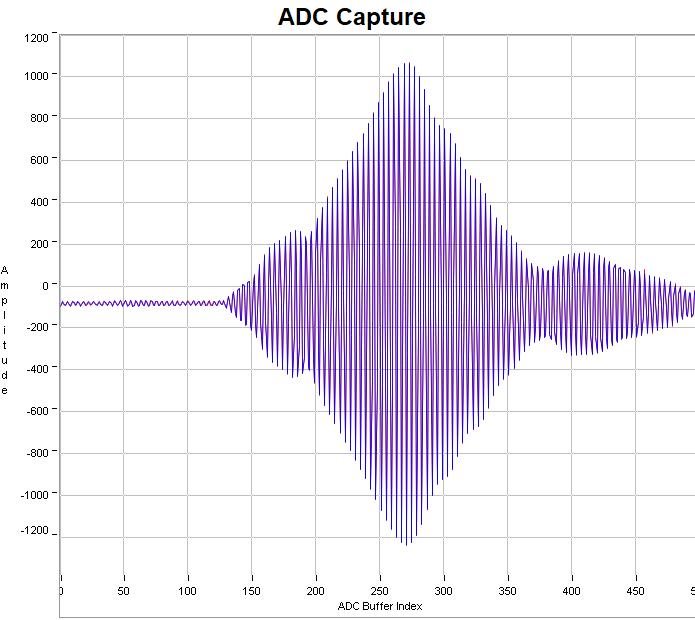
    2. I have enabled the USS_CALIBRATE_SIGNAL_GAIN_TEST and set the USS_AGC_CONSTANT to 60. On the ADC capture the signal is offset by about 70-80 units (see image attached). I was wondering if that can be adjusted using USS_ALG_CALIBRATED_UPS_DC_OFFSET? Again, please point me at the relevant part of the documentation if I am missing something. Any other recommendations on what parameters I could test? I saw a filtering capability but I have not tested it yet.

    3. Finally, I could not find a lot of information on how the calibration tab and algorithm works. I assume it is better or faster than using gain correction factor, but I do not quite understand how it works.

    What is the best places for the alphaMin flows? How can I calculate the slope and the offset myself?

  • Kostyantyn,

    Sorry for the delay.   I looking into these questions and will provide a detailed response tomorrow.

  • 1. To change the measurement rate, you would need to change USS_APP_CAPTURE_DELAY_ACLK in USS_App_userConfig.h. 32768 are the number of cycles for 1 second interval. For example, if you wanted 0.5 second interval, use 16,384. In hmi.c, you can see that the maximum value is 65535 or 2 seconds. 

    2. Still looking into exactly how this DC offset works.  I will provide details as soon as possible.

    3. The calibration tab is only functional for the water firmware at this time.  For gas, you could set a single calibration point using the meter constant.  #11 in the FAQ below discusses calculating the meter constant.

    http://www.ti.com/lit/an/slaa837a/slaa837a.pdf   

  • I understand that the USS_APP_CAPTURE_DELAY_ACLK changes the default measurement rate. 

    The issue is that the function resultsCalcVolume that calculates that cumulative volume of gas that has passed through the meter uses "rate", which is DC_User_Params->gap_ups_ups, passed to it in results_Update.

    However, DC_User_Params->gap_ups_ups is not set by default and hence the calculation does not work.

    The workaround that I am using currently is using setting it directly in HMI_Init(void) as below:

    DC_User_Params->gap_ups_ups = 100;

    HMI_update_USSsleepDuration();

    I do not think this is the best way to do this.

    The other issue with the calculation in resultsCalcVolume is that it does not take into account the measurement time (not sure about this though). 

    I noticed this when I calibrated the meter to display the correct VFR, but the volume on the display is much smaller (i.e. VFR x time > volume).

    In other boards with similar functionality I have used timestamps to calculated the time elapsed and hence volume, but I could not find this functionality in the firmware.

  • Kostyantyn,

    The workaround you have will work, but you may be better setting it at initialization.  In ussDCCommandHandlers.c, you could add the line of code below.

    COMAND_HANDLER gCommandHandler =
    {
            .appReqUpdate = false,
            .appReqData = false,
            .appReqCaptures = false,
            .updateValid = false,
            .updateCalib = false,
            .gap_ups_ups = 100,
    };

    In regards to the DC Offset, the GUI displays the ADC signal before the processing is applied, so no difference is seen in the GUI ADC capture.  It is recommended to use USS_APP_DC_OFFSET_CANCELLATION_ENABLE function.

    Since you have an offset, it is also recommended that you reduce the AGC constant so that you are seeing less than 1000 counts on the negative side of the signal.  This is to ensure you are not oversaturating the input.

    COMAND_HANDLER gCommandHandler =

    {

    .appReqUpdate = false,

    .appReqData = false,

    .appReqCaptures = false,

    .updateValid = false,

    .updateCalib = false,

    .gap_ups_ups = 100,

    };

  • Just wanted to follow up with some additional information regarding the DC offset.  If you want to view the offset that is applied, you can make the following change in USSLibGUIApp.c.  Notice that HMI_PostMeasurement_Update(); has been moved to be after run algorithms.  The GUI will now show the corrected DC offset in the ADC Capture tab.

                    // HMI function called after measurement and before algorithms
                    // are executed.
                    // Used to send ADC waveforms before manipulation
                   // HMI_PostMeasurement_Update();  //comment this out
    
                    code = USS_runAlgorithmsFixedPoint(&gUssSWConfig,&algResFixed);
                    if ( (USS_message_code_valid_results != code) &&
                         (USS_message_code_algorithm_captures_accumulated != code) )
                    {
                        //Invalid algorithm results, report error
                        USSLibGUIApp_send_error(COMMAND_HANDLER_ERROR_FAULT_ALG_ERROR,
                                                (uint16_t) code);
                    }
                    HMI_PostMeasurement_Update();   //move update here to view in GUI after DC offset has been applied
                    // HMI function called after algorithms are executed
                    // Used to send results of algorithms.
                    HMI_PostAlgorithm_Update(&algResFixed);
                }
            }

    Another note about using the DC offset cancellation function.  This needs to be enabled by uncommenting the #define USS_APP_DC_OFFSET_CANCELLATION_ENABLE in USS_App_userconfig.h.  After uncommenting, be sure that you also set the interval as well using the code below.  The default is 0(disabled).  The value you use will determine the interval based on measurement cycles.  If it is set to 1, this will be performed for every measurement, 2 is every 2nd measurement, and so on.  

    #define USS_APP_DC_OFFSET_CANCELLATION_INTERVAL     (1)

  • Thank you Eddie, everything works (at least on my experimental setup)!

    I have also tried bypassing the AFE all together. It works, but the DC offset is quite large (so your code is very useful).

    I have already sent the meter for testing, so not quite sure how the DC offset affects the accuracy.

    I might put together another meter soon and test that.

    Regarding the timing and cumulative volume calculations, what are your recommendations on that? Are you planning to implement an algorithm for the volume calculation, or should I start looking into it myself? For now, I have experimentally determined a multiplier that I use to get the right VFR -> volume calculation, but that is clearly not a good way to do it.

  • You should see some slightly better drift performance on the dToF when using the DC offset. 

    We are not planning to implement an algorithm for determining accumulated volume in firmware.  In the GUI, we just multiply the flow rate by the time on every measurement.  If you were to implement in firmware, you could potentially reduce the number of cycles required for the math by only performing this multiplication every so often as long as you know the interval stays the same between measurements.  Something like VFR1 + VFR2 + VFR3..., then multiply by the time it takes for the number of measurements accumulated.  If you need to update a display frequently, this might not work well since you will only calculate the volume accumulated every so often.          

**Attention** This is a public forum