This thread has been locked.

If you have a related question, please click the "Ask a related question" button in the top right corner. The newly created question will be automatically linked to this question.

EVM430-FR6043: XPBO pin for generating a high pulse.

Part Number: EVM430-FR6043
Other Parts Discussed in Thread: MSP430FR6043

Hello,

This is the question with the follow up on the previous one.

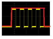
I need to generate a pulse signal which has a width of the total number of pulses generated at the output of the Channel_0 out pin of the MSP430FR6043. the signal which needs to be generated is as shown below for better understanding. below you can see 4 pulses generated at the output (yellow) and (red) pulse signal which is desired to be generated on the XPBO pin which is free to use in the current evaluation board.
Then I tried to vary the RExN pin to fit the pulses but it is not possible. Then I decided to use the XPBO pin i.e Pin P7.0 which is not used in the current program. So with the help of Google, I wrote a small program to make the P7.0 pin high and then again make it low and also the main point here is to find the perfect loop to place this program so I can get the desired signal (red).

I tried a few loops and the results are as shown below.
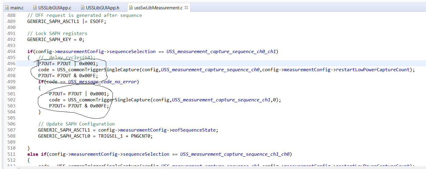
I got the pulse signal which covers both the pulse upstream and downstream. 

My question:

Where can I find the perfect loop to place my program where i can generate the desired pulse signal as shown above.

Thank you

BR

Jadhav

  • Hello Jadhav,

    As a lot of these functions are automatically implemented, it is a bit more complicated.  See my notes below.

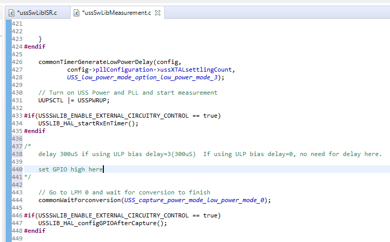
    Where to set the GPIO high:  

    See image below and my notes.  In order to get the timing correct, you may need to add a 300uS delay before setting the pin high if you are using the ULP Bias delay set to 3.  3 is the default setting.

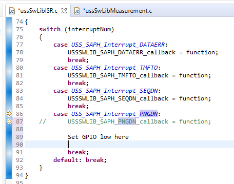
     Where to set the GPIO low:


    See image below.  Be sure that you are also commenting out the USSSWLIB_SAPH_PNGDN_callback and replacing it with your code to set the GPIO low.


  • Hello Eddie,

    Thank you for your reply.

    I am using the XPBO pin i.e the port 7.0 pin for generating the pulse signal. I am using the basic high and low command as follows:

    P7OUT= P7OUT | 0x0001;  // to make port 7.0 high.

    P7OUT= P7OUT & 0x00FE; // to make port 7.0 low.

    after making the changes in the program as told by you. I got the XPBO pin high forever.

    I used the delay command as follows:

    __delay_cycles(3); // delay before making pin high.

    What am i doing wrong. Can you check on your board and show me the output?

    Thank you.

    BR

    Jadhav

  • Hello Eddie,

    Please follow the below reply

    Thank you.

    BR

    Jadhav

  • Hello Eddie,

    I want to update you on this thread. I have successfully generated the required signal. There are 3 things I want to point out.

    1 - I have used a delay command to generate the signal. Which gives me the freedom to vary the pulse width of the signal by just changing the delay value.

    2. I have used the following code:

    __delay_cycles(3150);             // delay to match the TX pulse start.

    P7OUT= P7OUT | 0x0001;      // GPIO high.

    __delay_cycles(630);               // __delay_cycles("signal width").

    P7OUT= P7OUT & 0x00FE;    // GPIO low.

    with this logic, I have the required signal but I have 2 problems with this. 

    - 1st: The generated signal has high jittering. (suggest a solution)

    - 2nd: on power reset of the board the position of the pulse signal is changed, and thus have to reflash the program and run it again. (suggest a solution)

    3. which clock does the above-mentioned delay command use. 

    Thank you

    BR

    Jadhav

**Attention** This is a public forum