This thread has been locked.

If you have a related question, please click the "Ask a related question" button in the top right corner. The newly created question will be automatically linked to this question.

MSP430G2452: Handling Low Power Mode and Interrupts

Part Number: MSP430G2452


Hi All,

Fairly new to programming micro-controllers in C and I have been having some difficulty optimizing low power mode while keeping my interrupts short, like in this blog post. Was wondering if anyone could give me some advice on how to proceed. 

Basically what I am trying to accomplish is setting up my device in main(), then waiting for an interrupt in low power mode before executing the corresponding code. Currently, I have this set up as follows, with the bulk of the code inside the ISR:

...
__bis_SR_register(CPUOFF + GIE); // Enter LPM0 and enabling interrupts while(1) //Loop forever {}
}
// Port 1 interrupt service routine
#pragma vector=PORT1_VECTOR
__interrupt void Port_1(void)
{  
   WDTCTL = WDTPW + WDTCNTCL;
   P1IFG &= ~BIT3;  // P1.3 IFG (interrupt flag) cleared
   trig += 1; // Cycling through 'trig' values to activate different LEDs sequentially
   
   if(trig == 4){
     trig = 0x000;
   }
   if(trig == 1){
     LED = BIT1;
   } else if (trig == 2) {
     LED = BIT3;
   } else if (trig == 3) {
     LED = BIT5;
   } else if (trig == 0){
     LED = 0x000;
   }
} 

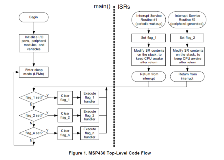
As this is just a short example and this method would eventually lead to very large ISRs, something I am trying my best to avoid, I would like to poll using interrupts in low power mode and then deal with the triggered actions within main(). The following diagram I found online seems to suggest this is possible but I cannot figure out how to check a condition with the CPU off.

I have tried running the following script but keep returning an error as a condition cannot be evaluated in LPM0. Does anyone know of another way of handling this? Perhaps something similar to the MSP432's wait for interrupt (WFI) function which I believes halts code execution until an interrupt is generated? 

{...
__bis_SR_register(CPUOFF + GIE); // Enter LPM0 and enabling interrupts

while(1) { //Loop forever
   if(trig == 4){
     trig = 0x000;
   }
   if(trig == 1){
     LED = BIT1;
   } else if (trig == 2) {
     LED = BIT3;
   } else if (trig == 3) {
     LED = BIT5;
   } else if (trig == 0){
     LED = 0x000;
   }
__bis_SR_register(CPUOFF + GIE);  // 
}
}

// Port 1 interrupt service routine
#pragma vector=PORT1_VECTOR
__interrupt void Port_1(void)
{  
   WDTCTL = WDTPW + WDTCNTCL;
   P1IFG &= ~BIT3;  // P1.3 IFG (interrupt flag) cleared
   trig += 1; // Cycling through 'trig' values to activate different LEDs sequentially
   __bic_SR_register_on_exit(LPM0_bits + GIE);        // Exiting LMP0 on exit from interrupt, disabling interrupts until task in main is compete

} 

  • >  have tried running the following script but keep returning an error as a condition cannot be evaluated in LPM0.

    I'm not sure I understand this sentence. What error are you seeing? Where is it coming from? (Compiler? Debugger? Simulator?)

    >  but I cannot figure out how to check a condition with the CPU off

    That diagram is overall very useful, but I think the wording "Modify SR  .." in the boxes on the right obscures the point. Imagine that the boxes contain only the text "Wake up main()" and don't dwell on the actual mechanism.

    ISRs can check conditions since the CPU is temporarily turned on to execute them. Once an ISR has waked up main(), the CPU is not off, so it can check conditions.

    The LPM mechanism is analogous to WFI (and AVR "sleep"), but with LPM the software (ISR), not the CPU, decides when to wake main()..

    --------------------

    I'm guessing that you're using the Launchpad push-button on P1.3 to simulate your device. Buttons are susceptible to "bounce". This is often a minor annoyance but here I'm concerned it will muddy your understanding of the flow. A simple debouncing mechanism looks like:

    __interrupt void PORT1_ISR(void) {
         __delay_cycles(2000);    // Spin for 2000 us (2ms) for debounce (probably long enough)
         P1IFG &= ~BIT3;            // Clear now that it has stopped bouncing
         if ((P1IN & BIT3) == 0) {  // Button low (i.e. pushed)?
            // Act on the button push here
         }
    }

    Yes, this introduces a spin-loop into an ISR, which normally you want to avoid. Consider it a concession to your "test fixture" -- most device signals do not "bounce" and thus do not need this code.

  • Hi Bruce,

    Thanks for the help! The error I was originally getting when attempting to execute a statement in LPM was:

    I ended up adding a __no_operation() function immediately after entering low power mode which seemed to resolve the situation, as this provided a line of code to hold on that did not require CPU action. I also realized that when using the LPM properly, the while loop I was using was not necessary and I was able to further simplify my code to use it in the manner you described. For others that may be having a similar problem, this is the final code I used:

    void main(void){
      WDTCTL = WDTPW + WDTHOLD; // Holding the watchdog timer
    ...
      P1IE |= BIT3;            // P1.3 interrupt enabled
      P1IES |= BIT3;           // P1.3 Hi/lo edge select
    ...
    while(1){       // Loops forever
        
        __bis_SR_register(CPUOFF + GIE);    // Entering LPM0 and enabling global interrupts
        __no_operation();     // Holds on this function when in LPM, continues to execute main after interrupt, holds again on each loop iteration
        
        // Do work in main, triggered by interrupt (in this case I am reading RGB values and activating corresponding LEDs)
        i2c_send_sequence(VALS_read,9,RGB_Trans,0);      // Reads values and stores them in the array RGB_Trans
        while(!i2c_done());  // Checks to make sure send/read process complete
          
        // Storing RGB values in a 3 byte array
        RGB_Data[0] = (RGB_Trans[3] << 8) | RGB_Trans[2]; // Appends high and low byte to get sensor value
        RGB_Data[1] = (RGB_Trans[5] << 8) | RGB_Trans[4];
        RGB_Data[2] = (RGB_Trans[7] << 8) | RGB_Trans[6];
          
        if(RGB_Data[0] >= RGB_Data[1] && RGB_Data[0] >= RGB_Data[2]){       
          P2OUT = BIT1; 
          P2IFG &= ~BIT1;       
        } else if(RGB_Data[1] >= RGB_Data[0] && RGB_Data[1] >= RGB_Data[2]){        
          P2OUT = BIT3;
          P2IFG &= ~BIT3;
        } else{
          P2OUT = BIT5;
          P2IFG &= ~BIT5;
        }
      }
    }
    
    // Port 1 interrupt service routine
    #pragma vector=PORT1_VECTOR
    __interrupt void Port_1(void)
    {  
       P1IFG &= ~BIT3;  // P1.3 IFG (interrupt flag) cleared (button)
       __bic_SR_register_on_exit(LPM0_bits);   // turns off low power mode on exit from interrupt
    }
    

    Thanks for the debouncing tip as well, that was not a problem I was aware of.

    Cheers,

    Charlie

**Attention** This is a public forum