This thread has been locked.

If you have a related question, please click the "Ask a related question" button in the top right corner. The newly created question will be automatically linked to this question.

EVM430-FR6047: Ultrasonic Design Center: Calibrating clamped-on transducers to work with metal pipe

Part Number: EVM430-FR6047
Other Parts Discussed in Thread: EVM430-FR6043

Hello,

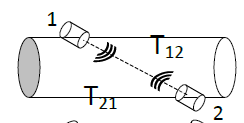
I am currently evaluating EVM430-FR6047 board and using Ultrasonic Design Center to play arround TI USSW Library. I have been using Audiowell pipe with fitted transducers in it (intrusive solution), and I successfully calibrated it to show the water flow rate in 1/2" pipe. Currently, I would like to move to non-intrusive solution (two 1MHz ultrasonic transducers clamped on the metal 1/2" pipe - 5cm distance between transducers). Unfortunately, I am unable to adjust the parameters in Ultrasonic Design Center to get correct ADC Capture. I am looking for any piece of advice, what to fix in the calibration.

1) This is what I get with default configuration:

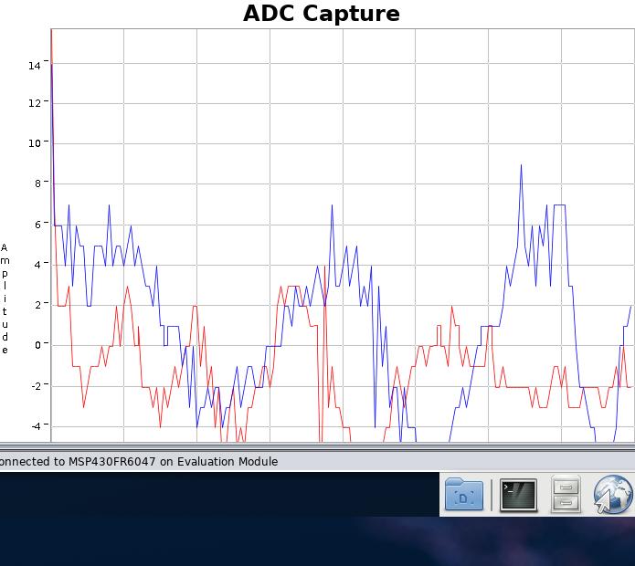
2) I dont get any errors and ADC capture look rather correct when I send a bigger amount of pulses (eg. 63) (This graph is obtained for the configuration with time of 28 us between pulse and ADC capture). However, when no water is flowing I still get this waveform, and I theoretically I shouldn't


I would be most grateful for any help or tips how to configure the Ultrasonic Design Center to work with transducers clamped in non-intrusive way.

Best,

Wojciech

  • Hello Wojciech,

    Clamp on metering does present some challenges due to the attenuation of the signal and signals riding along the pipe.  You also need to be sure that you have good clamping and couplant between the transducer and pipe.  Mechanical design is key here.    

    I have done some evaluation using PVC pipes which do not have as much attentuation as a metal pipe.  For this I have been fixing the transducers directly across from each other as shown below.    

    The image below shows my test pipe for zero flow measurements.  I have 1MHz transducers from Audiowell which have a 50 degree face and I place Magnalube-G as my couplant between the transducer and pipe.  A 2 piece 3D printed fixture is used to mount the transducers and held together with 2 hose clamps.  I am getting a good clean signal with this configuration using 22.8dB gain with the internal PGA.     

    For metal pipes, you will likely need some external amplification on the receive side to get a proper signal and it is expected you will see more noise.  I still need to do more research on this, but I am experimenting with using the EVM430-FR6043 which includes external amplification on the receive side.  I will still need to change some of the filtering components and external amplification needs to be enabled in the software FR6043 demo software example.

    From the wave form you show, you should first try to get a good signal at zero flow.  Again, you will probably need external amplification, but you could try without it.  Make sure your mechanical design is good and couplant is used and not dry.  You could try to reduce the gap between pulse start and ADC capture and increase the capture duration as it looks like you are not capturing the first part of the signal.  To reduce the gap without errors, you will probably need to increase the Start PPG count.  The thread below shows the relationship between the two.  This will give a better idea of what the signal looks like. 

    http://e2e.ti.com/support/microcontrollers/msp430/f/166/p/761932/2817850#2817850 

  • Hi Eddie,

    First of all thank you very much for your answer!

    I have few questions about what you wrote?

    1) Have you tested two-transducers-on-one-side configuration for clamp-on metering? What's the comparison between this approach, and the one you used?

    2) Does FR6043 work with water metering? I thought it is only for gas applications?

    3) How did you design the 3d printed thing? Do you happen to have design files? I would be most grateful for help in this matter. What are the guidelines when designing part like this?

    I am looking forward to hearing back from you.

    Best,.

    Wojciech

  • 1. We have not tested with both transducers on one side.  The signal level will be lower this way, but you would have the possibility for a wider dynamic range since the path traveled through the medium is longer.  For some customers, this may be an easier method to install.  Also, smaller pipe sizes would likely prefer this to get a longer path through the medium.

    2. Yes, FR6043 can also work with water similar to FR6047.  The results we have observed are similar as well.  I am working on a TI Design which will describe how to use the EVM430-FR6043 for water which will be released in the next few weeks.  The latest software for water metering does include FR6043 project for water as well.  That software can be found below.

    http://software-dl.ti.com/msp430/msp430_public_sw/mcu/msp430/USSSWLib/USSSWLibWater/latest/    

    There are also a couple of hardware changes which must be made to the EVM430-FR6043 for water.  See below.  After these changes and software update, the board operates with the GUI just like the EVM430-FR6047.

    Hardware modifications for water meter operation

    • Replace R75 and R80 with 1000pF cap, replace R77 and R78 with 200 ohm resistor, and place 0 ohm resistors on R76 and R79.
    • Remove all jumpers on J9. Transducers will connect to outside pins as pictured below.
    • Remove jumper from JP2, JP3, JP4, JP5, and J31.
    • The transducer connections on J9 can be seen below.

    3. This was designed in OpenSCAD.  I have attached the SCAD file and .stl design files.  You could modify this to meet your needs as well.  Basically, you are looking for something that will be able to clamp tightly to the pipe and angle the transducers properly.  The transducers that I am using have a 50 degree face, so the holders for the transducers are angled at 50 degrees with the diameter matching our transducers.  The transducers are pushed in to fit tightly against the outside wall of the pipe.parametric_clamp_on.scadparametric_clamp_on.stl  

**Attention** This is a public forum