This thread has been locked.

If you have a related question, please click the "Ask a related question" button in the top right corner. The newly created question will be automatically linked to this question.

EVM430-FR6043: TX RX crosstalk

Part Number: EVM430-FR6043
Other Parts Discussed in Thread: TS5A9411

Hi,
I'm testing the EVM with a pair of transducer (MCUSD13A300B09RS) 300 kHz for Air Flow measurement.

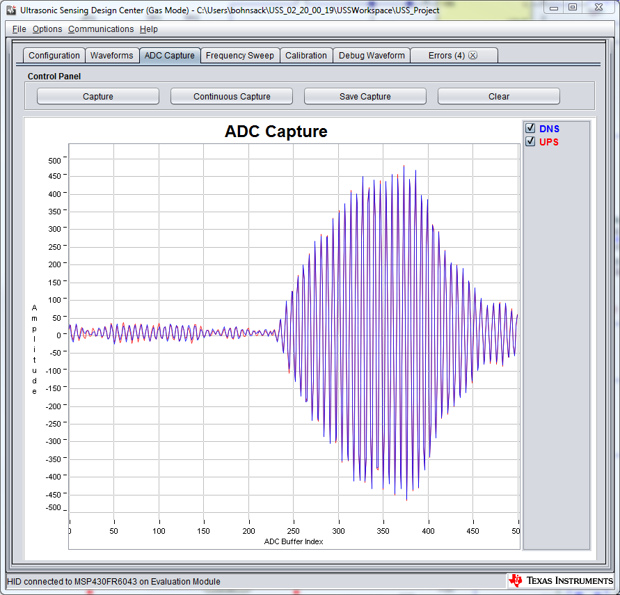
I was wondering about a huge signal right after the pulses are transmitted like in this ADC Capture:
Absolute TOF should be around 260us so this is way to early for a reflection.

<?xml version="1.0" encoding="UTF-8"?>
<ussMspGui>
	<settings>
		<isLogging>true</isLogging>
		<logLocation>C:\Users\bohnsack\USS_02_20_00_19\USSWorkspace\USS_Project</logLocation>
	</settings>
	<configParams>
		<target>gas</target>
		<board>EVM430-FR6043</board>
		<device>MSP430FR6043</device>
		<lph_gpm>lph</lph_gpm>
		<f1f2>300.0 310.0</f1f2>
		<patternSeq>2</patternSeq>
		<gapBetweenPulseAndCapture>150.0</gapBetweenPulseAndCapture>
		<numberOfPulses>24.0</numberOfPulses>
		<gapBetweenUpsAndDns>8000.0</gapBetweenUpsAndDns>
		<gapBetweenDnsAndUps>1000.0</gapBetweenDnsAndUps>
		<gainControl>4.4</gainControl>
		<areaConstant>61.00</areaConstant>
		<xt2Freq>8000</xt2Freq>
		<sigSamplingFreq>2000.0</sigSamplingFreq>
		<adcSamplePulse>40</adcSamplePulse>
		<deltaTOFOffset>0.0</deltaTOFOffset>
		<absTOFAdditionDelay>0.0</absTOFAdditionDelay>
		<captureDuration>250.0</captureDuration>
		<intrplCorrTableSize>0</intrplCorrTableSize>
	</configParams>
	<devModeParams>
		<param1>3</param1>
		<param2>100.0</param2>
		<param3>10000.0</param3>
		<param4>1000.0</param4>
		<param5>20000.0</param5>
		<param6>120.0</param6>
		<param7>10000.0</param7>
		<param8>128.0</param8>
		<param9>9.0</param9>
		<param10>0.0</param10>
	</devModeParams>
</ussMspGui>

So I did the following test:
- Transducer on J5 is disconnected and replaced by a 820 Ohm resistor for termination.
- Scope connected with Channel 1 to Transducer on J6 Pin 1
- Channel 2 connected to AFE_CH0_IN Signal on J9 Pin 4

The expected result would be to see on Channel 1 the TX Pulses and a constant voltage on Chanel 2 as no signal can be received.
What I got is this:

When the pulses are transmitted there is a small signal on Channel 2. After the Pulses are transmitted, there is quite a large Signal on the AFE_CH0_IN  signal. I guess thats part of the signal I'm seeing in the ADC Capture flag.
After the excitation of TX transducer is finished it continues ringing and the signal goes below -0.5 V. This seems to couple to the RX signal.

Is this normal or is there something wrong with my setup?

Best Regards,
Arne

  • Arne,

    We have not seen this kind of effect with the transducers we have tested. Figure 13 in the TI Design below shows what the typical waveform looks like. I think this may have something to do with the transducer type that you are using. It looks like they are intended for use with very high voltage excitation(up to 400Vp-p) and the waveform in the MCUSD13A300B09RS datasheet does show some ringing, though it is not zoomed in very well. I am not exactly sure why this is coupling to the RX line though. It could be happening where the ringing is coupling from TX to RX when switching occurs, but I can't say for sure because we have never seen this before. I recommend using a transducer that is designed for flow measurement. In the TI Design below, we have tested with 200kHz, 400kHz, and 500KHz transducers from a variety of manufacturers. These are rated for lower voltage and intended for use with air and gas flow applications where the MCUSD13A300B09RS is intended for level measurement and proximity so characteristics will be different.  

    http://www.ti.com/lit/ug/tiduej6/tiduej6.pdf

  • Hi Eddie,
    thank you for the reply I will try to get better suitable transducers.

    As it seems to be that only the ringing with amplitudes below -0.3 V is coupling to the RX path, one guess would be that coupling is happening inside the TS5A9411 multiplexer. As the Absolute Maximum Ratings of TS5A9411 only allow analog signals above -0.3 V the ringing of the transducer exceeds this.

  • Arne,

    Agreed that it could be happening inside the TS5A9411.  Let me know if you still see an issue with different transducers, but I suspect you will not.

  • I have achieved a clean signal now with the following modifications to the board:

    1. Removed U7 and U8 and shorted pins 5&6 of both pads. Measurement is now only working in one direction now so this is not practical. But this removed the corsstalk during ringing almost completely!
    2. Removed R49 and placed the Resistor on R59 instead and connected to ground. So the SIGNAL_RX is not connected to U9 anymore. This also helped reducing the crosstalk.
    3. Added more capacity (10uF each) to C38, C37, C41, C32, C27. Only small effect on signal quality
    4. Replaced R49 and R47 with 200 Ohm for a better TX signal quality

    So most of the crosstalk is caused by the multiplexers U7 and U8 and by the level shifter U9.
    There is still a bit crosstalk left during and after the TX phase, which propably could be removed by changing the layout and clearly seperating TX and RX paths.
    The measurement results of TOF are still not very good but this may be caused by the transducers.

    ADC Capture with transducers connected:

    Scope image with 820 Ohm resistor connected as RX transducer like in the test before:

**Attention** This is a public forum