This thread has been locked.

If you have a related question, please click the "Ask a related question" button in the top right corner. The newly created question will be automatically linked to this question.

MSP430F5659: Intermittent resets when writing to flash

Part Number: MSP430F5659
Other Parts Discussed in Thread: MSP-FET

Hi Everybody,


I am running into a hard to track down a bug that I am wondering if anyone can give any input as to things to check out. Our company has a product that utilizes flash for factory settings. On certain pcb's we are running into unexpected resets. The tricky thing about this bug is that when using the debugger it always fails between the first and second call to __write_extended_byte() however the exact location changes from run to run. Below is the section of the code in both C and the disassembly window that roughly causes the problem. Ultimately I am running out of ways to attempt to debug this and I was hoping somebody may be able to give a good suggestion for how to attack this problem. Thanks for all your feedback!

C Code
void WriteFlashWords(uint32_t xAddress, void *xData, uint16_t bytes)
{
uint16_t *data = (uint16_t *)xData;
uint16_t offset;
uint16_t tmp_SR; // holds a temporary copy of the CPU Status Register
uint16_t bytes_1 = bytes - 1;

if (bytes == 0)
{
return;
}

// There are currently only three areas of Flash that LJ3 devices (loggers, sensors, and testers) should ever be writing to:
// * Settings sectors
// * FOTA image sectors (note: some devices like the loggers will not store FOTA images in internal Flash protected here)
// * All the INFO memories -- see ProductDefs.h for definition
if( ((SETTINGS_SECTORS_START <= xAddress) && (xAddress+bytes < SETTINGS_SECTORS_END)) ||
((FOTA_IMG_SECTORS_START <= xAddress) && (xAddress+bytes < FOTA_IMG_SECTORS_END)) ||
((INFO_MEM_SECTOR_START <= xAddress) && (xAddress+bytes < INFO_MEM_SECTOR_END)) )
{
// Get a copy of the Status Register so we can tell at the end of the function if
// interrupts need to be re-enabled or not...
tmp_SR = __get_register(0x2);

// Make sure interrupts are disabled ...
__disable_interrupt();

FCTL3 = FWKEY; // clear main lock -- doesn't impact LOCKA since writing a 0 to LOCKA doesn't clear it
FCTL1 = FWKEY + WRT; // write mode

// Write an even number of bytes...
for(offset = 0; offset < bytes_1; offset += 2)
{
// Do we need to conditionally check the address where we're going to write?
__write_extended_word(xAddress + offset, data[offset/2]); // write word at a time for better efficiency
}

// Handle the odd byte...
if (bytes > offset)
{
__write_extended_byte(xAddress + offset, data[offset/2]);
}

FCTL1 = FWKEY; // clear erase bit
FCTL3 = FWKEY + LOCK; // (main) lock -- caller should lock LOCKA if needed

// Re-enable interrupts if necessary...
if((tmp_SR & GIE) == GIE)
{
__enable_interrupt();
}
}
else
{
ASSERT(false);
}
}

Disassembly

// Write an even number of bytes...
for(offset = 0; offset < bytes_1; offset += 2)
0b43 CLR.W R11
0c3c JMP 0x10b90
--- flash.c -- 81 ------------------------------------------
{
// Do we need to conditionally check the address where we're going to write?
__write_extended_word(xAddress + offset, data[offset/2]); // write word at a time for better efficiency
0f4a MOV.W R10, R15
0e49 MOV.W R9, R14
0e5b ADD.W R11, R14
0f63 ADC.W R15
0d4b MOV.W R11, R13
5d03 RRUM.W #1, R13
0d5d RLA.W R13
0d57 ADD.W R7, R13
2d4d MOV.W @R13, R13
b113c840 CALLA #0x140c8 <___write_extended_word>
}
2b53 ADD.W #2, R11
0b95 CMP.W R5, R11
f22b JNC 0x10b78
--- flash.c -- 85 ------------------------------------------
// Handle the odd byte...
if (bytes > offset)
0b98 CMP.W R8, R11
0b2c JC 0x10bae
--- flash.c -- 88 ------------------------------------------
{
__write_extended_byte(xAddress + offset, data[offset/2]);
0f4a MOV.W R10, R15
0e49 MOV.W R9, R14
0e5b ADD.W R11, R14
0f63 ADC.W R15
0d4b MOV.W R11, R13
5d03 RRUM.W #1, R13
0d5d RLA.W R13
0d57 ADD.W R7, R13
2d4d MOV.W @R13, R13
b113b440 CALLA #0x140b4 <___write_extended_byte>
--- flash.c -- 90 ------------------------------------------
}
FCTL1 = FWKEY; // clear erase bit
b24000a54001 MOV.W #0xa500, &0x0140
FCTL3 = FWKEY + LOCK; // (main) lock -- caller should lock LOCKA if needed
b24010a54401 MOV.W #0xa510, &0x0144
--- flash.c -- 94 ------------------------------------------
// Re-enable interrupts if necessary...
if((tmp_SR & GIE) == GIE)
36b2 BIT.W #8, R6
0124 JZ 0x10bc0
--- flash.c -- 97 ------------------------------------------
{
__enable_interrupt();
32d2 EINT
063c JMP 0x10bce
--- flash.c -- 99 ------------------------------------------
}
}
else
{
ASSERT(false);
3f401c8c MOV.W #0x8c1c, R15
3e406700 MOV.W #0x0067, R14
b113620a CALLA #0x10a62 <_assert>
7417 POPM.W R4-R11
1001 RETA

  • Hi Calvin,

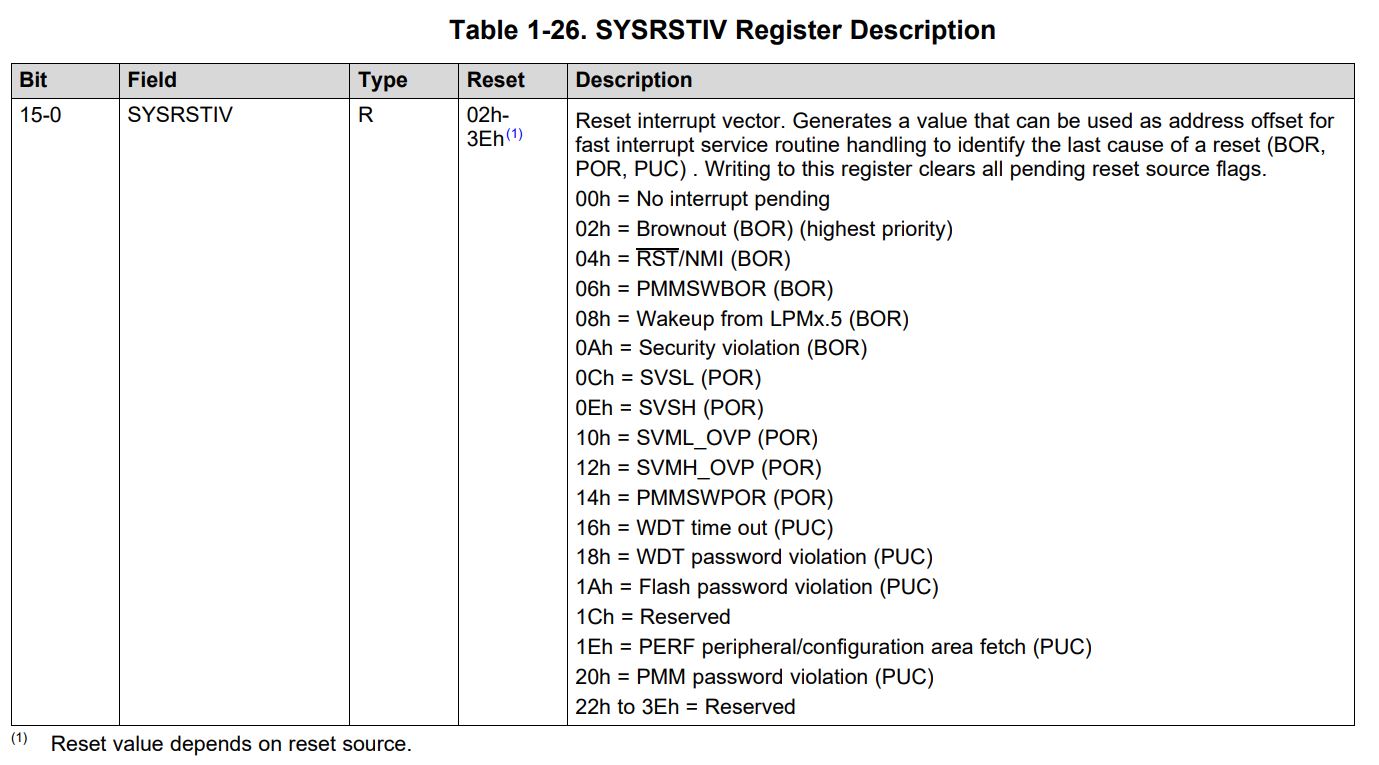
    Could you log the SYSRSTIV to see what's the reset source?

    And did enable WATCHDOG function?

  • Hi Calvin,

    checking the RST source is great and I would assume you will get a WDT reset because you device might hang in the programmign procedure. But please confirm this!

    Does this behavior depend if you program odd or even number of bytes because depending on this different code is executed correct. Out of your code post its hard to see where the flash write appears.

    Can you please post the IDE picture (CCS or IAR) with the code Window and the Disassembly next to each other and even pointer if you can point me in the disassembly to where the write (must be a pointer operation or indirect addressing) appears.

  • Hey all,

    I am another engineer working with Calvin on the same project.

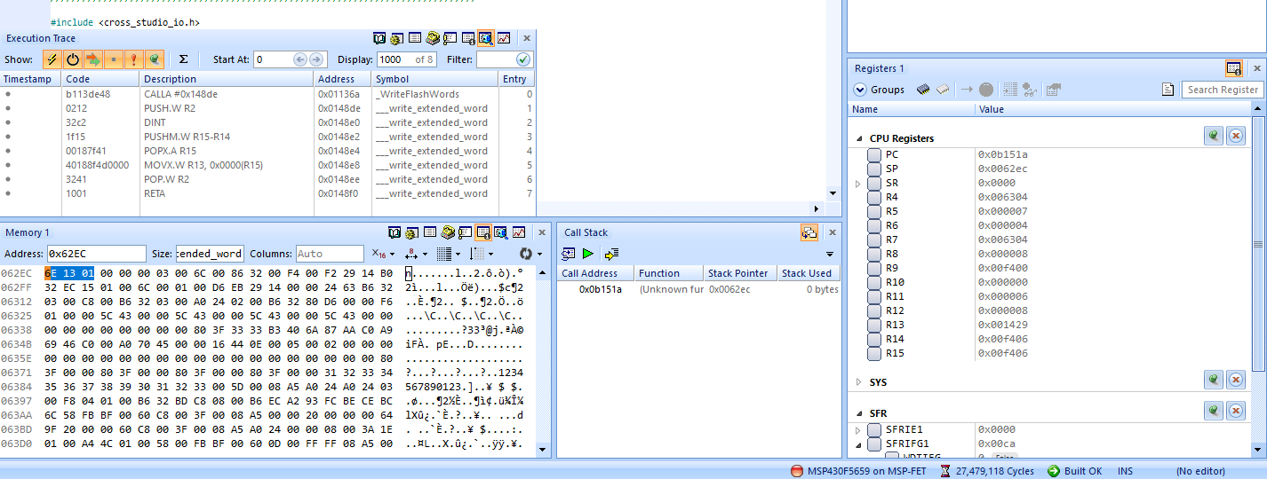
    What specifically we are seeing is that occasionally on return from the __write_extended_word() function (it doesn't happen every time), the program counter value seems to be bogus (see attached pic that it's 0x0B151A, after the RETA instruction in the execution trace). Enabling the vacant memory access interrupt also corroborates that the bogus PC value (which will usually point to vacant memory) seems to be the cause of the execution hang. This will happen with or without a debugger (MSP-FET) attached. I've also included a picture of the stack at the time of RETA, and the stack pointer and the value at that point in the stack (0x01136E) are as they should be.

    For what it's worth, we have an external watchdog timer on the product. The processor will not reset after the issue until the external watchdog pulls down the ~RST/NMI pin. Occasionally the PC will point to an area of BSL memory which will cause the RST vector to be 0xA (security violation). We haven't yet caught a case where the PC points to memory that actually has our application code in it.

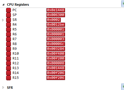
    Our only clue is that, rarely, the lower order byte of the PC will match what's in R13 (the register from which __write_extended_word() will take the value to write to extended flash, as seen in the MOVX.W R13, 0x0000(R15) instruction). I've also attached a picture of that situation.

    Edit: now that I see the title of the forum post, I guess a more accurate one would have been "Intermittent hangs when writing to flash"


  • Hi Christopher,

    thanks for detailed information. The level of detail is highly appreciated and helps to better support you.

    Some questions for alignment:

    1. You operate your write instructions from 0x1136E means the higher part of the memory correct?

    2. The location you want to write is stored in R15 = 0xF406 correct and the value you write is in R13 0x1429 correct.

    3. So the PC after the RETA is random right? Can be in the BSL area or vacant memory area correct?

    4. It sounds that you somehow can reproduce it even if not 100% relialbe correct? Do you see this on all units you test?

    5. Is this a production problem or do you experience this in the field?

    So can you please share the disassembly window for the area around the RETA?

    Also the complete Disassembly of the flash write function woudl be important to analyse in detail.

    Meanwhile maybe you can try to inser a nop after the RETA with inline assembler if possible.

  • 1.) The compiler/linker (CrossStudio for MSP430, for what it's worth) puts our flash write instructions in the extended memory, yes. The actual flash settings live in the lower 64K.
    2.) That does look like what __write_extended_word() is doing, yes.
    3.) The PC after the RETA in __write_extended_word() does occasionally appear to be bogus. It's not completely random and will usually be one of 5 to 7 values for a given build of the code. Another frustrating aspect of the problem is that enough arbitrary code changes, even in code paths unrelated to the flash functions, will prevent the issue from appearing on certain units.
    4.) The issue seems to follow the CPU, as we've swapped the CPUs on known failing units onto known passing units and it will turn passing units into failing (and vice versa). We haven't discovered a way purely in firmware to replicate the issue on known passing units. We don't see the issue on most of our units and I'd have to look at the production database to see how many 1 out of n units may have failed production tests due to non-responsiveness. We just noticed a larger incidence of failures in the past couple months (since May 2019; the current production firmware version has been out since November 2018).
    5.) Boards with this issue will become unresponsive and not pass our production tests, so at least in theory there aren't any units with this issue making it into the field.

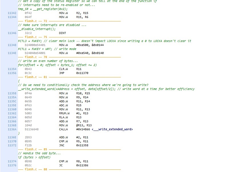
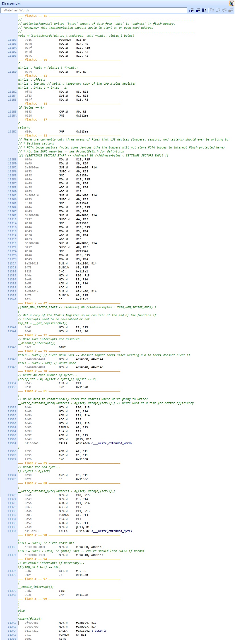
    I've attached to this post the disassembly of our function around the RETA, the full disassembly of our function, and the disassembly of __write_extended_word() (and __write_extended_byte()). You can see the C code (in green) interleaved with the disassembly.

  • Hi Christopher,

    thanks for detailed answers and the disassembly. It does not look that bad. I searched for 2 write instructions following each other quickly.

    The fact that a flash write triggers the internal oscillator can be critical if the write is finished (clock request removed) and another write appears immedialty after that clock removal. But I cannot see this sequence in your code. After each write you have a POP followed by a RETA going back into the for loop.

    But what I see is that you populate R12 and then do the RETA. So therefore it would be interesting how you stack pointer and STACK is looking like in fail case.

    Can it be that you corrupt you STACK somehow? The initial post shows it at 0x6300 which is at the TOP right? Can it be that it was incremented by one word too much?

    Also can you please let me know with which frequency you are operating and with which Vcore setting?

  • Hello Dietmar,

    I watched a failing unit and a passing unit use our WriteFlashWords() function and didn't see a difference in their stack transactions in the IDE's memory viewer. I did notice that the product firmware was operating at 16 MHz (DCO and XT2) without setting up VCORE to level 2 as TI documentation (family guide, datasheet, examples, etc.) recommends, which is bizarre since it's a pretty common MSP430-ism (this firmware is pretty old and has had several developers across its history). I'm curious why we haven't been seeing this issue more.

    The PMMVCOREx register seems to be persistent across code re-flashes, so on a failing unit we put on firmware to set VCORE up to 2, then put on the old firmware (so the instructions and their locations in flash should be exactly the same as when they were failing, the only difference being the PMM peripheral), and the unit seems to pass. I will get back to you on how this solution works on a sample of 10 or more failing units.

  • Hi Christopher,

    great finding. This is very critical if you overclock the CPU without alignend Vcore to the correct level you can see all kind of unpreditctable behaviors.

    Please correct and let me know if it fixes the problem. Please follow the procedure recommended in the user guide or in the Driver Lib.

    You need to increase Vcore step by step and not from 0 to level 2 directly. Also take care that the high and low site supervisors are configured correctly during Vcore increase. As mentioned this is described in the users guide but I recommend to use the Driver Lib functions which are realizing it for you.

  • Hi Dietmar,

    I should have specified we used the pmm.c library function to set VCORE up in steps.

**Attention** This is a public forum