This thread has been locked.

If you have a related question, please click the "Ask a related question" button in the top right corner. The newly created question will be automatically linked to this question.

MSP430FR5994: Problem with data transmissions via UART

Part Number: MSP430FR5994

Hi,

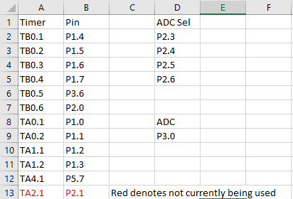
So I have a problem of where I'm sending back ADC data to a computer via UART. I have 11 channels for the ADC, I need to know which channel is which on the computer side of what I'm receiving. The problem that I can't seem to find a elegant solution to is how to know which channel the data is for. 

The ADC data comes out between 0x0FFF and 0x0000. On the computer side, I check the 2 bytes to see if there's a 0 in the MSByte (most significant byte) and if there isn't then the data is flipped. If I instead use that 0 in the MSByte to do 0-B to do channel designations then I cannot know which one is the correct first two bytes. If I send an arbitrary two bytes then I won't be able to tell if it's an ADC result or the actual channel designation. Any ideas? I'm using python with PySerial to communicate with the MSP430FR5994.

Thanks!

  • Hello Msega,

    Thanks for your posting.

    We will look into this for you and get back ASAP.

    Thanks,

    Yiding

  • Any updates?

  • Hello Msega,

    Have you considered using ADC ISRs to send the data? In order for the computer to know which ADC sent the data, you could send an extra byte for the channel designation before sending the data for a total of 3 bytes. This would allow the computer to both recognize the channel and check to see if the data is flipped because the MSbyte is no longer being utilized to check for the channel. In the ISR for the ADC channels, you can have a switch statement with a case for each channel and within each case, send the respective designation and the data. 

    Let me know if this helps.

    All the best,

    Colin Adema

  • I think that would work. Also, I have another problem (I'm not sure if I'm supposed to start a new post but, hopefully this should be a quick answer). So I actually have an ADC that runs on one channel (Channel 12 specifically) and I have 4 selects. I have a 16-1 mux that the ADC is connected to in the common pin. The selects are pins 2.6-2.3. They're all connected correctly. When running my code and stepping through the program my channel 0 is channel 0 for the ADC result. When I let the program run at the normal speed it now is giving me the channel 10 result (from hardware) as channel 0 in CCS. Do you have any ideas of why this would be happening? If more info is needed (eg. setup/code) I can provide all of that. I'm using an msp430fr5994 on a protoboard that is connected to the launchpad's EZ-FET. 

    Edit: Also thanks for the help!

  • Hello,

    I'll look into this, but just to make sure I understand the problem, you're putting a decimal 10 (so a binary 1010) on pins 2.6-2.3, and instead of seeing channel 10 on the output, you see channel 0?

    If you have some code that would show the setup and execution of this, that would be a big help.

    All the best,

    Colin Adema

  • I have a counter (in my case "j") that outputs 0-10 to P2OUT by doing P2OUT = (j<<3). When it gets to j = 10 it writes to ADC_Holder[j] where j is supposed to be 10 but instead it writes to ADC_Holder[0] for some reason. I'll be able to send the code tomorrow morning, I have to leave work in a few minutes. But yes, essentially what you're saying is correct. I'll post the setup and code tomorrow.

  • Is similar behavior observed with different numbers? Such as if j = 11, instead of writing to ADC 11 it writes to ADC 1?

  • So, I just tested that. If I increased the size of ADC_Holder to a size of 11, then adjust the code that the ADC value will send the 11th one to the 10th place of the array. It actually just writes the 11th ADC channel to ADC_Holder[0]. This behavior is really weird, unless I'm just overlooking something simplistic. 

    Here's the code (I removed anything to do with the UART as I'm using the oscillator from pins PJ.4 and PJ.5 and my protoboard doesn't have those currently on there).

    #include <msp430.h> 
    
    
    /****************************************************************
     * File: ********
     * Author: *********
     * Date: *********
     * Description: Will take in external voltage requirements for each of the
     * 11 pins via UART. Will then set the output voltage of each of those timer pins
     * to the assigned voltage. The ADC is ran to make sure that the voltage desired is
     * as closely followed from the external circuit.
     * Setup:
     * PWM OUT -> 1k Resistor -> ADC Pin -> 47 uF Cap -> GND
     ****************************************************************/
    
    
    int TimerVal[11] = {400,400,400,400,400,400,400,400,400,400,400};
    volatile int ADC_Holder[11];
    int PowConv[11];
    unsigned int i = 0;
    unsigned int j = 0;
    unsigned int k = 0;
    unsigned int l = 0;
    unsigned int m = 0;
    unsigned int n = 0;
    unsigned int ADC_Flag = 0;
    int part1, part2;
    int cat1, cat2;
    int Recieved[44];
    int UART_Transmit;
    
    void ADC_Setup(void);
    void Timer_Setup(void);
    void Pin_Setup(void);
    unsigned Concatentate(unsigned, unsigned);
    void UART_Recieve_Vals(void);
    void UART_Setup(void);
    void Timer_Setter(void);
    
    void main(void)
    {
    	WDTCTL = WDTPW | WDTHOLD;	// stop watchdog timer
    	Pin_Setup();
    	//UART_Setup();
    	ADC_Setup();
    	Timer_Setup();
    	__bis_SR_register(GIE);
    
    	//while(i<44){} /turn on
    	i = 0;
    	//UART_Recieve_Vals(); /turn on
    	ADC12CTL0 |= (ADC12ENC | ADC12SC);
    
    	for(n = 0; n<11; n++)
    	{
    	    PowConv[n] = 2048;
    	}
        __delay_cycles(1000);
    
    	while(1)
    	{
    	    __delay_cycles(20000);
    
            if(ADC_Holder[m] > PowConv[m]+5 && TimerVal[m] > 0) //if ADC result is greater than desired power decrease duty cycle
                TimerVal[m] -= 1;
            else if(ADC_Holder[m] < PowConv[m]-5 && TimerVal[m] < 1000) //if ADC result is lower than desired power increase duty cycle
                TimerVal[m] += 1;
            Timer_Setter();
    /*	    UART_Transmit = ADC_Holder[m];
    	    part1 = UART_Transmit & 0x00FF;
    	    part2 = (UART_Transmit & 0xFF00) >> 8;
            while(!(UCA3IFG & UCTXIFG));
            UCA3TXBUF = part2;
            while(!(UCA3IFG & UCTXIFG));
            UCA3TXBUF = part1;
            if(i == 44)
            {
                UART_Recieve_Vals();
                i=0;
            }*/
            m++;
            if(m == 11)
            {
                m = 0;
            }
    	}
    }
    
    //Receives a half word and will increment the counter
    /*#pragma vector = EUSCI_A3_VECTOR
    __interrupt void USCI_A3_ISR(void)
    {
        switch(UCA3IV)
        {
        case USCI_NONE: break;
        case USCI_UART_UCRXIFG:
            while(!(UCA3IFG&UCTXIFG));
                Recieved[i] = UCA3RXBUF;
                i++;
            break;
        case USCI_UART_UCTXIFG:  break;
        case USCI_UART_UCSTTIFG: break;
        case USCI_UART_UCTXCPTIFG: break;
        default: break;
        }
    }*/
    
    //Will change the Mux selects and also take the ADC measurement and determine whether the TimerVal needs to be
    //incremented or decremented
    #pragma vector = ADC12_B_VECTOR
    __interrupt void ADC12_ISR(void)
    {
        P2OUT = (j << 3);
        ADC_Holder[j] = ADC12MEM12;
        j++;
        if(j==11)
        {
            j=0;
        }
    
        ADC12IFGR0 &= ~ADC12IFG12;
    }
    
    //ADC Setup - Read comments in function
    void ADC_Setup(void)
    {
        ADC12CTL0 = ADC12SHT0_2 | ADC12ON | ADC12MSC;      // Sampling time, S&H=16, ADC12 on
        ADC12CTL1 =  ADC12PDIV_3 | ADC12DIV_7 | ADC12SHP | ADC12CONSEQ_2 | ADC12SSEL_3;   // Use sampling timer; Single channel
        ADC12CTL2 |= ADC12RES_2;                // 12-bit conversion result
        ADC12CTL3 |= ADC12CSTARTADD_12;          //Starting ADC channel is ch0
        ADC12MCTL12 |= ADC12INCH_12;              //A2 ADC input select; Vref=AVCC
        ADC12IER0 |= ADC12IE12;                  //Interrupt enables for channel 0
    }
    
    //Pin Setup
    void Pin_Setup(void)
    {
        ///////////////////// Mux Sel
        P2DIR |= BIT6 | BIT5 | BIT4 | BIT3;
    
        ///////////////////// ADC
        P3SEL1 |= BIT0;
        P3SEL0 |= BIT0;
        P3DIR &= ~BIT0;
        ///////////////////// Timer
        P1DIR |= BIT7 | BIT6 | BIT5 | BIT4 | BIT3 | BIT2 | BIT1 | BIT0;
        P1SEL0 |= BIT7 | BIT6 | BIT5 | BIT4 | BIT3 | BIT2 | BIT1 | BIT0;
        P1SEL1 &= ~BIT7;
    
        P2DIR |= BIT0;
        P2SEL0 |= BIT0;
    
        P3DIR |= BIT6;
        P3SEL0 |= BIT6;
        P3SEL1 &= ~BIT6;
    
        P5DIR |= BIT7;
        P5SEL1 |= BIT7;
        ///////////////////// UART
        //P6SEL1 &= ~(BIT0 | BIT1);
        //P6SEL0 |= (BIT0 | BIT1);                // USCI_A3 UART operation
        //PJSEL0 |= BIT4 | BIT5;                  // For XT1
    
        PM5CTL0 &= ~LOCKLPM5;
    }
    
    //Setting timer period to 1000 cycles,
    void Timer_Setup(void)
    {
        TBCCR0 = 1000-1;
        TA0CCR0 = 1000-1;
        TA1CCR0 = 1000-1;
        TA4CCR0 = 1000-1;
    
        TBCCTL1 = OUTMOD_7; // Reset/Set
        TBCCTL2 = OUTMOD_7;
        TBCCTL3 = OUTMOD_7;
        TBCCTL4 = OUTMOD_7;
        TBCCTL5 = OUTMOD_7;
        TBCCTL6 = OUTMOD_7;
        TA0CCTL1 = OUTMOD_7;
        TA0CCTL2 = OUTMOD_7;
        TA1CCTL1 = OUTMOD_7;
        TA1CCTL2 = OUTMOD_7;
        TA4CCTL1 = OUTMOD_7;
    
        Timer_Setter();
    
        TBCTL = TASSEL_2 | MC_1 | TBCLR; //SMCLK, Up mode, Timer Clear
        TA0CTL = TASSEL_2 | MC_1 | TACLR;
        TA1CTL = TASSEL_2 | MC_1 | TACLR;
        TA4CTL = TASSEL_2 | MC_1 | TACLR;
    }
    
    void UART_Setup(void)
    {
         // XT1 Setup
         CSCTL0_H = CSKEY_H;                     // Unlock CS registers
         CSCTL2 = SELA__LFXTCLK | SELS__DCOCLK | SELM__DCOCLK;
         CSCTL3 = DIVA__1 | DIVS__1 | DIVM__1;   // Set all dividers
         CSCTL4 &= ~LFXTOFF;
         do
         {
             CSCTL5 &= ~LFXTOFFG;                // Clear XT1 fault flag
             SFRIFG1 &= ~OFIFG;
         } while (SFRIFG1 & OFIFG);              // Test oscillator fault flag
         CSCTL0_H = 0;                           // Lock CS registers
    
         // Configure USCI_A3 for UART mode
         UCA3CTLW0 = UCSWRST;                    // Put eUSCI in reset
         UCA3CTLW0 |= UCSSEL__ACLK;              // CLK = ACLK
         UCA3BRW = 3;                            // 9600 baud
         UCA3MCTLW |= 0x5300;                    // 32768/9600 - INT(32768/9600)=0.41
                                                 // UCBRSx value = 0x53 (See UG)
         UCA3CTLW0 &= ~UCSWRST;                  // Initialize eUSCI
         UCA3IE |= UCRXIE;                       // Enable USCI_A3 RX interrupt
    }
    unsigned Concatentate(unsigned x, unsigned y)
    {
        return x * 10 + y; //concatenating numbers
    }
    
    //Puts the 2 half words together into one full 4 digit number (hex)
    void UART_Recieve_Vals(void)
    {
        l = 0;
        for(k = 0; k < 44; k+=4)
        {
            cat1 = Concatentate(Recieved[k],Recieved[k+1]);
            cat2 = Concatentate(cat1,Recieved[k+2]);
            PowConv[l] = Concatentate(cat2,Recieved[k+3]);
            l++;
        }
    }
    
    //Sets the timer capture control register to the timer values
    void Timer_Setter(void)
    {
        TBCCR1 = TimerVal[0];
        TBCCR2 = TimerVal[1];
        TBCCR3 = TimerVal[2];
        TBCCR4 = TimerVal[3];
        TBCCR5 = TimerVal[4];
        TBCCR6 = TimerVal[5];
        TA0CCR1 = TimerVal[6];
        TA0CCR2 = TimerVal[7];
        TA1CCR1 = TimerVal[8];
        TA1CCR2 = TimerVal[9];
        TA4CCR1 = TimerVal[10];
    }
    

    Additionally here's a few pictures of the setup. 

    Description of setup: 11 circuits setup in this manner (PWM output pin -> 1k resistor -> ADC input + 47 uF cap -> gnd). 

    We're not currently using TA2.1 because a software PWM is required to use it and we didn't want to complicate things anymore throwing in another ISR into the code. 

    P2.6 is MUX Sel 3, P2.5 MUX Sel 2, P2.4 MUX Sel 1, P2.3 MUX Sel0

    Showing VCC, EN, and GND connections as well as the selects. (We didn't have any rubbing alcohol to remove the flux, so it's a little messy)

    Hopefully you can see the solder joints aren't jumpered. Was also confirmed with an x-ray. 


    Connections to MSP430.

    Overall setup: Going from top down is channel 0-10 on the left hand side. All power and gnd rails on the breadboard are setup as expected. 

    Thanks!

    Edit: Additionally, thinking that possibly something was wrong with the select signals or something like that, I hooked up a logic analyzer to the 4 selects and saw that it would start at 0 and count up to 10 as expected. Here's a picture of it as well. 

  • Thanks for all the info! I'll starting picking it apart and see what could be wrong.

    Regards,

    Colin Adema

  • Hello,

    After doing some testing, I've noticed that the ADC value always lags behind and gets stored in the next array spot, i.e. 7 gets stored in 8, 10 gets stored in 0 like you found, etc. I'm currently working to see why this is the case.

    All the best,

    Colin Adema

  • Yea, I also noticed that. I completely forgot to mention that. Sorry about that. 

    Thanks for the in depth troubleshooting!

  • Could it be this warning that I'm getting?

    "warning #10421-D: For FRAM devices running at higher than 8MHz, FRAM waitstate needs to be configured accordingly."

  • Unfortunately, that did not solve the issue. This was the code that I got from MSP430FR5x9x Demo - Configure MCLK for 16MHz operation

    void FRAM_Setup(void)
    {
        // Configure one FRAM waitstate as required by the device datasheet for MCLK
        // operation beyond 8MHz _before_ configuring the clock system.
        FRCTL0 = FRCTLPW | NWAITS_1;
    
        // Clock System Setup
        CSCTL0_H = CSKEY_H;                     // Unlock CS registers
        CSCTL1 = DCOFSEL_0;                     // Set DCO to 1MHz
        // Set SMCLK = MCLK = DCO, ACLK = VLOCLK
        CSCTL2 = SELA__VLOCLK | SELS__DCOCLK | SELM__DCOCLK;
        // Per Device Errata set divider to 4 before changing frequency to
        // prevent out of spec operation from overshoot transient
        CSCTL3 = DIVA__4 | DIVS__4 | DIVM__4;   // Set all corresponding clk sources to divide by 4 for errata
        CSCTL1 = DCOFSEL_4 | DCORSEL;           // Set DCO to 16MHz
        // Delay by ~10us to let DCO settle. 60 cycles = 20 cycles buffer + (10us / (1/4MHz))
        __delay_cycles(60);
        CSCTL3 = DIVA__1 | DIVS__1 | DIVM__1;   // Set all dividers to 1 for 16MHz operation
        CSCTL0_H = 0;                           // Lock CS registers
    }

    Still observed the same problem with channel 10 going into channel 0 and the rest being moved up.

  • So I found the issue, essentially when coding the ADC ISR, for some foolish reason I thought that the ADC would convert while reading the memory data. While it should convert -> set flag high -> go into ISR. As such the P2OUT should have changed before sampling the channel. As such P2OUT must be initialized to clear bits 6 through 3 before starting the ADC. Additionally, the ADC ISR code was changed to: 

    #pragma vector = ADC12_B_VECTOR
    __interrupt void ADC12_ISR(void)
    {
        ADC_Holder[j] = ADC12MEM12;
        j++;
        P2OUT = (j << 3);
        ADC_Flag = 1;
        if(j==11)
        {
            j=0;
            P2OUT = (j << 3);
        }
    
        ADC12IFGR0 &= ~ADC12IFG12;
    }

    This ensures that P2OUT is changed before the next ADC conversion happens. Thanks helping Colin. If anyone else finds this code and decides to use it, I have not ensured that the code works 100%, although the bug has been fixed that was described earlier in this thread.

  • Msega,

    Wonderful to hear you got it working. Let me know if you have any other issues and/or want additional input on sending the data through UART.

    All the best,

    Colin Adema

**Attention** This is a public forum