This thread has been locked.

If you have a related question, please click the "Ask a related question" button in the top right corner. The newly created question will be automatically linked to this question.

MSP430F5529: MSP430F5529 USB related issues

Part Number: MSP430F5529
Other Parts Discussed in Thread: MSP430WARE,

My customer is using MSP430F552x , they have raised the follow query -


1. We are using Thru' Hole  24MHz crystal  on XT2IN and XT2OUT to use XT2CLK as clock source for our application including USB.

2. Now to run at lower frequency (MCLK, SMCLK,ACLK)  i.e 12 MHZ , we internally divided the clock by 2.


In source code we configured the clock as under:


UCSCTL4 |= 0x0555;                                          // SMCLK=MCLK=XT2

UCSCTL5 = DIVM__2 + DIVS__2 + DIVA__2;   // CPU Freq : 12.0 MHz


and for USB Clock we did :


#define USB_CRYSTAL_X2  24000000UL


UCS_setExternalClockSource (0, USB_CRYSTAL_X2);


With this requirement and configuration  we need to get confirmation;


a. whether USB Factory boot loader will work 

b. USB application (CDC class ) can function.

c. Our normal application code function


If the above is possible, then what more configuration we need to do.Please provide us the configuration code to do the same.


  • Default factory loaded USB BSL will work with 24 MHz XT2. TI USB stack (as it is, by default target is 5529, 4 MHz XT2) will work with 24 MHz XT2. If I remember right, by default MCLK source in TI USB stack is DCO, but it should work with XT2 / 2 without problems. Don't have time to check register setup, but if I remember right, there is some GUI for TI USB stack easy setup.

  • Hello Anatya,

    Anatya Vallabh said:
    My customer is using MSP430F552x , they have raised the follow query -

    Thanks for posting the question on E2E.

    Anatya Vallabh said:

    1. We are using Thru' Hole  24MHz crystal  on XT2IN and XT2OUT to use XT2CLK as clock source for our application including USB.

    2. Now to run at lower frequency (MCLK, SMCLK,ACLK)  i.e 12 MHZ , we internally divided the clock by 2.


    In source code we configured the clock as under:


    UCSCTL4 |= 0x0555;                                          // SMCLK=MCLK=XT2

    UCSCTL5 = DIVM__2 + DIVS__2 + DIVA__2;   // CPU Freq : 12.0 MHz

    This appears to be correct. Depending on your needs, you don't have to source ACLK from XT2 but instead could use a 32kHz crystal on XT1 to source ACLK. If you don't, then this should be fine.

    I would highly recommend using our 'MSP430F55xx_UCS_08.c' code example as a reference. The main difference here is that the MCLK/SMCLK/ACLK are not divided by 2 and possibly different XT2 drive strengths. For your design, it may be good to measure MCLK/SMCLK/ACLK on the pins used in the code example to confirm the frequency is correct.

    MSP430F55xx_UCS_08.c

    /* --COPYRIGHT--,BSD_EX
     * Copyright (c) 2012, Texas Instruments Incorporated
     * All rights reserved.
     *
     * Redistribution and use in source and binary forms, with or without
     * modification, are permitted provided that the following conditions
     * are met:
     *
     * *  Redistributions of source code must retain the above copyright
     *    notice, this list of conditions and the following disclaimer.
     *
     * *  Redistributions in binary form must reproduce the above copyright
     *    notice, this list of conditions and the following disclaimer in the
     *    documentation and/or other materials provided with the distribution.
     *
     * *  Neither the name of Texas Instruments Incorporated nor the names of
     *    its contributors may be used to endorse or promote products derived
     *    from this software without specific prior written permission.
     *
     * THIS SOFTWARE IS PROVIDED BY THE COPYRIGHT HOLDERS AND CONTRIBUTORS "AS IS"
     * AND ANY EXPRESS OR IMPLIED WARRANTIES, INCLUDING, BUT NOT LIMITED TO,
     * THE IMPLIED WARRANTIES OF MERCHANTABILITY AND FITNESS FOR A PARTICULAR
     * PURPOSE ARE DISCLAIMED. IN NO EVENT SHALL THE COPYRIGHT OWNER OR
     * CONTRIBUTORS BE LIABLE FOR ANY DIRECT, INDIRECT, INCIDENTAL, SPECIAL,
     * EXEMPLARY, OR CONSEQUENTIAL DAMAGES (INCLUDING, BUT NOT LIMITED TO,
     * PROCUREMENT OF SUBSTITUTE GOODS OR SERVICES; LOSS OF USE, DATA, OR PROFITS;
     * OR BUSINESS INTERRUPTION) HOWEVER CAUSED AND ON ANY THEORY OF LIABILITY,
     * WHETHER IN CONTRACT, STRICT LIABILITY, OR TORT (INCLUDING NEGLIGENCE OR
     * OTHERWISE) ARISING IN ANY WAY OUT OF THE USE OF THIS SOFTWARE,
     * EVEN IF ADVISED OF THE POSSIBILITY OF SUCH DAMAGE.
     *
     *******************************************************************************
     * 
     *                       MSP430 CODE EXAMPLE DISCLAIMER
     *
     * MSP430 code examples are self-contained low-level programs that typically
     * demonstrate a single peripheral function or device feature in a highly
     * concise manner. For this the code may rely on the device's power-on default
     * register values and settings such as the clock configuration and care must
     * be taken when combining code from several examples to avoid potential side
     * effects. Also see www.ti.com/grace for a GUI- and www.ti.com/msp430ware
     * for an API functional library-approach to peripheral configuration.
     *
     * --/COPYRIGHT--*/
    //******************************************************************************
    //  MSP430F552x Demo - XT2 sources MCLK & SMCLK
    //
    //  Description: This program demonstrates using XT2 to source MCLK. XT1 is not
    //  connected in this case.
    //
    //  By default, LFXT1 is requested by the following modules:
    //     - FLL
    //     - ACLK
    //  If LFXT1 is NOT used and if the user does not change the source modules,
    //  it causes the XT1xxOFIFG flag to be set because it is constantly looking
    //  for LFXT1. OFIFG, global oscillator fault flag, will always be set if LFXT1
    //  is set. Hence, it is important to ensure LFXT1 is no longer being sourced
    //  if LFXT1 is NOT used.
    //  MCLK = XT2
    //
    //               MSP430F552x
    //             -----------------
    //        /|\ |                 |
    //         |  |                 |
    //         ---|RST              |
    //            |            XT2IN|-
    //            |                 | HF XTAL (455kHz - 16MHz)
    //            |           XT2OUT|-
    //            |                 |
    //            |             P7.7|--> MCLK = XT2
    //            |             P2.2|--> SMCLK = XT2
    //
    //   Bhargavi Nisarga
    //   Texas Instruments Inc.
    //   April 2009
    //   Built with CCSv4 and IAR Embedded Workbench Version: 4.21
    //******************************************************************************
    
    #include <msp430.h>
    
    int main(void)
    {
      WDTCTL = WDTPW + WDTHOLD;                 // Stop watchdog timer
    
      P2DIR |= BIT2;                            // SMCLK set out to pins
      P2SEL |= BIT2;                            
      P7DIR |= BIT7;                            // MCLK set out to pins
      P7SEL |= BIT7;
      
      P5SEL |= BIT2+BIT3;                       // Port select XT2
    
      UCSCTL6 &= ~XT2OFF;                       // Enable XT2 
      UCSCTL3 |= SELREF_2;                      // FLLref = REFO
                                                // Since LFXT1 is not used,
                                                // sourcing FLL with LFXT1 can cause
                                                // XT1OFFG flag to set
      UCSCTL4 |= SELA_2;                        // ACLK=REFO,SMCLK=DCO,MCLK=DCO
    
      // Loop until XT1,XT2 & DCO stabilizes - in this case loop until XT2 settles
      do
      {
        UCSCTL7 &= ~(XT2OFFG + XT1LFOFFG + DCOFFG);
                                                // Clear XT2,XT1,DCO fault flags
        SFRIFG1 &= ~OFIFG;                      // Clear fault flags
      }while (SFRIFG1&OFIFG);                   // Test oscillator fault flag
    
      UCSCTL6 &= ~XT2DRIVE0;                    // Decrease XT2 Drive according to
                                                // expected frequency
      UCSCTL4 |= SELS_5 + SELM_5;               // SMCLK=MCLK=XT2
    
      while(1);                                 // Loop in place
    }

  • Anatya Vallabh said:

    and for USB Clock we did :


    #define USB_CRYSTAL_X2  24000000UL


    UCS_setExternalClockSource (0, USB_CRYSTAL_X2);

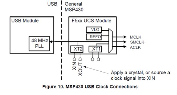
    With regards to USB, the user's guide documentation seems to indicate that the internal 48-MHz USB PLL gets sourced directly from XT2. Thus, for a 24-MHz crystal, you will need to make sure the register settings (e.g. UPQB, UPMB, DIVQ, DIVM, etc.) are configured correctly for CLKSEL = 24 MHz. Table 42-2 in the user's guide shows those register values. It looks like you're mixing register-level code with DriverLib-level code - it may be helpful and easier for developing/debugging to use one or the other, not both. This function seems correct but again I would recommend referring to our DriverLib code examples such as 'ucs_ex4_XTSourcesDCOInternal.c' in MSP430Ware.

    ucs_ex4_XTSourcesDCOInternal.c

    /* --COPYRIGHT--,BSD
     * Copyright (c) 2017, Texas Instruments Incorporated
     * All rights reserved.
     *
     * Redistribution and use in source and binary forms, with or without
     * modification, are permitted provided that the following conditions
     * are met:
     *
     * *  Redistributions of source code must retain the above copyright
     *    notice, this list of conditions and the following disclaimer.
     *
     * *  Redistributions in binary form must reproduce the above copyright
     *    notice, this list of conditions and the following disclaimer in the
     *    documentation and/or other materials provided with the distribution.
     *
     * *  Neither the name of Texas Instruments Incorporated nor the names of
     *    its contributors may be used to endorse or promote products derived
     *    from this software without specific prior written permission.
     *
     * THIS SOFTWARE IS PROVIDED BY THE COPYRIGHT HOLDERS AND CONTRIBUTORS "AS IS"
     * AND ANY EXPRESS OR IMPLIED WARRANTIES, INCLUDING, BUT NOT LIMITED TO,
     * THE IMPLIED WARRANTIES OF MERCHANTABILITY AND FITNESS FOR A PARTICULAR
     * PURPOSE ARE DISCLAIMED. IN NO EVENT SHALL THE COPYRIGHT OWNER OR
     * CONTRIBUTORS BE LIABLE FOR ANY DIRECT, INDIRECT, INCIDENTAL, SPECIAL,
     * EXEMPLARY, OR CONSEQUENTIAL DAMAGES (INCLUDING, BUT NOT LIMITED TO,
     * PROCUREMENT OF SUBSTITUTE GOODS OR SERVICES; LOSS OF USE, DATA, OR PROFITS;
     * OR BUSINESS INTERRUPTION) HOWEVER CAUSED AND ON ANY THEORY OF LIABILITY,
     * WHETHER IN CONTRACT, STRICT LIABILITY, OR TORT (INCLUDING NEGLIGENCE OR
     * OTHERWISE) ARISING IN ANY WAY OUT OF THE USE OF THIS SOFTWARE,
     * EVEN IF ADVISED OF THE POSSIBILITY OF SUCH DAMAGE.
     * --/COPYRIGHT--*/
    //******************************************************************************
    //!  This program demonstrates using an external 32kHz crystal to supply ACLK,
    //!  and using a high speed crystal or resonator to supply SMCLK.
    //!  MLCK for the CPU is supplied by the internal DCO.  The 32kHz crystal
    //!  connects between pins Xin and Xout. The high frequency crystal or
    //!  resonator connects between pins XT2IN and XT2OUT.  The DCO clock is
    //!  generated internally and calibrated from the 32kHz crystal.
    //!  ACLK is brought out on pin P11.0, MCLK is brought out on P11.1,
    //!  SMCLK is brought out on P11.2.
    //!
    //!  ACLK = LFXT1 = 32768Hz, MCLK = default DCO = 32 x ACLK = 1048576Hz
    //!  SMCLK = HF XTAL
    //!   An external watch crystal between XIN & XOUT is required for ACLK
    //!
    //!                MSP430F54xA
    //!             -----------------
    //!        /|\ |              XIN|-
    //!         |  |                 | 32kHz
    //!         ---|RST          XOUT|-
    //!            |                 |
    //!            |                 |
    //!            |            XT2IN|-
    //!            |                 | HF XTAL or Resonator (add capacitors)
    //!            |           XT2OUT|-
    //!            |                 |
    //!            |            P11.0|-->ACLK = 32kHz Crystal Out
    //!            |                 |
    //!            |            P11.1|-->MCLK
    //!            |                 |
    //!            |            P11.2|-->SMCLK = High Freq Xtal or Resonator Out
    //!
    //! This example uses the following peripherals and I/O signals.  You must
    //! review these and change as needed for your own board:
    //! - UCS module
    //! - GPIO Port peripheral
    //!
    //! This example uses the following interrupt handlers.  To use this example
    //! in your own application you must add these interrupt handlers to your
    //! vector table.
    //! - None.
    //!
    //*****************************************************************************
    #include "driverlib.h"
    //*****************************************************************************
    //
    //Desired Timeout for XT1 initialization
    //
    //*****************************************************************************
    #define UCS_XT1_TIMEOUT 50000
    
    //*****************************************************************************
    //
    //Desired Timeout for XT2 initialization
    //
    //*****************************************************************************
    #define UCS_XT2_TIMEOUT 50000
    
    //*****************************************************************************
    //
    //XT1 Crystal Frequency being used
    //
    //*****************************************************************************
    #define UCS_XT1_CRYSTAL_FREQUENCY    32768
    
    //*****************************************************************************
    //
    //XT2 Crystal Frequency being used
    //
    //*****************************************************************************
    #define UCS_XT2_CRYSTAL_FREQUENCY   24000000
    
    //*****************************************************************************
    //
    //Variable to store returned STATUS_SUCCESS or STATUS_FAIL
    //
    //*****************************************************************************
    uint8_t returnValue = 0;
    
    //*****************************************************************************
    //
    //Variable to store current clock values
    //
    //*****************************************************************************
    uint32_t clockValue;
    
    //*****************************************************************************
    //
    //Variable to store status of Oscillator fault flags
    //
    //*****************************************************************************
    uint16_t status;
    
    void main (void)
    {
        //Stop WDT
        WDT_A_hold(WDT_A_BASE);
    
        //ACLK, MCLK, SMCLk set out to pins
        GPIO_setAsPeripheralModuleFunctionOutputPin(
            GPIO_PORT_P11,
            GPIO_PIN0 + GPIO_PIN1 + GPIO_PIN2
            );
    
        //Port select XT1
        GPIO_setAsPeripheralModuleFunctionInputPin(
            GPIO_PORT_P7,
            GPIO_PIN0 + GPIO_PIN1
            );
    
        //Initializes the XT1 and XT2 crystal frequencies being used
        UCS_setExternalClockSource(
            UCS_XT1_CRYSTAL_FREQUENCY,
            UCS_XT2_CRYSTAL_FREQUENCY
            );
    
        //Initialize XT1. Returns STATUS_SUCCESS if initializes successfully
        returnValue = UCS_turnOnLFXT1WithTimeout(
            UCS_XT1_DRIVE_0,
            UCS_XCAP_3,
            UCS_XT1_TIMEOUT
            );
    
        //Startup HF XT2 crystal Port select XT2
        GPIO_setAsPeripheralModuleFunctionInputPin(
            GPIO_PORT_P5,
            GPIO_PIN2 + GPIO_PIN3
            );
    
        //Initialize XT2. Returns STATUS_SUCCESS if initializes successfully
        returnValue = UCS_turnOnXT2WithTimeout(
            UCS_XT2_DRIVE_4MHZ_8MHZ,
            UCS_XT2_TIMEOUT
            );
    
        //Select XT1 as ACLK source
        UCS_initClockSignal(
            UCS_ACLK,
            UCS_XT1CLK_SELECT,
            UCS_CLOCK_DIVIDER_1
            );
    
        //Select XT2 as SMCLK source
        UCS_initClockSignal(
            UCS_SMCLK,
            UCS_XT2CLK_SELECT,
            UCS_CLOCK_DIVIDER_1
            );
    
        // Enable global oscillator fault flag
    	SFR_clearInterrupt(SFR_OSCILLATOR_FAULT_INTERRUPT);
        SFR_enableInterrupt(SFR_OSCILLATOR_FAULT_INTERRUPT);
    
        // Enable global interrupt
        __bis_SR_register(GIE);
    
        //Verify if the Clock settings are as expected
        clockValue = UCS_getMCLK();
        clockValue = UCS_getACLK();
        clockValue = UCS_getSMCLK();
    
        //Loop in place
        while (1) ;
    }
    
    #if defined(__TI_COMPILER_VERSION__) || defined(__IAR_SYSTEMS_ICC__)
    #pragma vector=UNMI_VECTOR
    __interrupt
    #elif defined(__GNUC__)
    __attribute__((interrupt(UNMI_VECTOR)))
    #endif
    void NMI_ISR(void)
    {
      do {
        // If it still can't clear the oscillator fault flags after the timeout,
        // trap and wait here.
        status = UCS_clearAllOscFlagsWithTimeout(1000);
      } while(status != 0);
    }

    Here, the XT2 frequency is set as follows.

    #define UCS_XT2_CRYSTAL_FREQUENCY   24000000

    Anatya Vallabh said:

    With this requirement and configuration  we need to get confirmation;


    a. whether USB Factory boot loader will work 

    b. USB application (CDC class ) can function.

    c. Our normal application code function

    a. Yes, according to Section 4.3.2 in the very helpful Starting a USB Design Using MSP430 MCUs app note, "If using the USB BSL for factory programming of the MSP430 device, only 4, 8, 12, and 24 MHz are auto-recognized by the BSL. See Section 3.6".

    b. Assuming the registers mentioned above are configured correctly and the guidelines in the Starting a USB Design Using MSP430 MCUs app note are followed, the CDC class should function correctly.

    c. Yes, the application will get executed using the 12-MHz MCLK.

    Besides the Starting a USB Design Using MSP430 MCUs app note, check out the MSP430 USB Developers Package for additional resources.

    Regards,

    James

  • Hello James ,

    This is in continuation to the query initiated by Mr. Anatya from TI. Thanks for your helpful information regarding last query on MCU Part no  MSP430F5529

    Please note we are not using any other clock source for our application except Crystal on XT2.

    Now We have the following queries/observations to make.

    1. Yes. TI's Factory USB boot loader works fine as we use 24 MHZ crystal directly on XT2 pins. 

         At present we are initiating BOOT LOADING by  powering on the device keeping  PUR pin held high externally.Now This option looks not viable in field for us as it needs hardware access.

         So we are trying the soft option. i.e  from our application code in main flash to  jump into factory bsl code 

        a) will it be correct option for field upgrade of MSP430 code?

        b) We would like to know what are the possible drawbacks of this method and what preventive actions in code or hardware we should take.

        c) is there any possibility that if something goes wrong in the process... like power  break / usb cable damage etc. during boot loading , can the same device be reprogrammed thru' boot loading in field after  

             power cycle ?

    2.  ...and regarding Application code & USB  function even though  MCLK & SMCLK divided down to 12 MHZ,.

    Yes, as you rightly pointed out and as per the above block in your Application doc, USB module directly takes the clock from XT2 crystal itself and not from MCLK ( hope i am correct in my statement !! ), USB does get detected but my MSP430 application USB communication  with PC Application GUI misses most of the data frame  now which was very smooth when MCLK was 24 MHZ. Apart from USB communication other functions are working fine now(all Interrupt timing has been configured now for 12MHz MCLK) . I feel there might be timing issue now as cpu freq is reduced by half.

    Please let me know any suggestion from your side to solve this. Any modification to do in usb driver library/api function etc in .c/.h files? if clock change doesn't affect usb library, then i will look for code optimizing for timing.

    During debugging we have noticed this  in code...may be it will help to get any clue :

    switch(USB_getConnectionState())
     {
       // This case is executed while your device is enumerated on the
       // USB host
    
       case ST_ENUM_ACTIVE:
    
        ........
        ........// <===== MY CODE REACHES HERE even when there is data loss
    
    }

    3. Also noticed second attachment of USB not recognized by PC i.e  COMM port not getting created.Observation is that when USB of MSP430F5529 Board is connected to PC first and then apply the board's aux supply USB CDC comm port  not getting created on PC. Please suggest what could be the cause and how we can resolve this.Any Modification in Hardware.

    4. After EMI/EMC noise test as per IEC standard performed on our another product board involving the subject mcu part , we found that VCORE pin voltage got reduced(< 1.0 V) .By further troubleshooting we found that external Capacitor ( 470nF as per datasheet recommendation) at VCORE pin malfunctions.How can we prevent such situation from happening?

    Appreciate your reply.

    Thanks,

    Arup

  • Hello Arup,

    Thanks for your post.

    Ars said:

    1. Yes. TI's Factory USB boot loader works fine as we use 24 MHZ crystal directly on XT2 pins. 

         At present we are initiating BOOT LOADING by  powering on the device keeping  PUR pin held high externally.Now This option looks not viable in field for us as it needs hardware access.

         So we are trying the soft option. i.e  from our application code in main flash to  jump into factory bsl code 

        a) will it be correct option for field upgrade of MSP430 code?

        b) We would like to know what are the possible drawbacks of this method and what preventive actions in code or hardware we should take.

        c) is there any possibility that if something goes wrong in the process... like power  break / usb cable damage etc. during boot loading , can the same device be reprogrammed thru' boot loading in field after  

             power cycle ?

    It's a good question. The software option is definitely possible and preferred for firmware updates in the field. Thankfully, there's a very detailed resource that discusses several different options and should cover all your questions called USB Field Firmware Updates on MSP430™ MCUs app note.

    Ars said:

    2.  ...and regarding Application code & USB  function even though  MCLK & SMCLK divided down to 12 MHZ,.

    Yes, as you rightly pointed out and as per the above block in your Application doc, USB module directly takes the clock from XT2 crystal itself and not from MCLK ( hope i am correct in my statement !! ), USB does get detected but my MSP430 application USB communication  with PC Application GUI misses most of the data frame  now which was very smooth when MCLK was 24 MHZ. Apart from USB communication other functions are working fine now(all Interrupt timing has been configured now for 12MHz MCLK) . I feel there might be timing issue now as cpu freq is reduced by half.

    Please let me know any suggestion from your side to solve this. Any modification to do in usb driver library/api function etc in .c/.h files? if clock change doesn't affect usb library, then i will look for code optimizing for timing.

    Clocking in USB applications is critical. The USB specification requires the XT2 crystal has a tolerance of ±2500 ppm or less. Please check that your crystal meets this spec. Since you did cut the system clock frequency in half, then there could be bandwidth issues. By that, I mean you may be spending too much time in an Interrupt Service Routine (ISR) now or your application code is disabling interrupts.

    I would encourage you to carefully go through Sections 12 Debugging Tips in the MSP430 USB API Programmer's Guide. There are many other helpful sections in this document as well, so please read through them. USB operation with the USB PLL enabled requires PMMCOREVx >= 2 for proper operation.

    Ars said:
    3. Also noticed second attachment of USB not recognized by PC i.e  COMM port not getting created.Observation is that when USB of MSP430F5529 Board is connected to PC first and then apply the board's aux supply USB CDC comm port  not getting created on PC. Please suggest what could be the cause and how we can resolve this.Any Modification in Hardware.

    I'm not sure what "apply the board's aux supply" means. Are you power cycling the MSP430? On the hardware side, please be sure that your design follows the recommendations in the MSP430 USB API Programmer's Guide and Section 4 in the Starting a USB Design Using MSP430 MCUs app note.

    Please be more specific on the flow of what you're doing here.

    Ars said:
    4. After EMI/EMC noise test as per IEC standard performed on our another product board involving the subject mcu part , we found that VCORE pin voltage got reduced(< 1.0 V) .By further troubleshooting we found that external Capacitor ( 470nF as per datasheet recommendation) at VCORE pin malfunctions.How can we prevent such situation from happening?

    Unfortunately, I am not an EMI/EMC expert. For CVCORE, is the capacitor ratio of CDVCC/CVCORE > 10 as mentioned in Section 5.3 in the datasheet? Are you using a capacitor with a tolerance better than +/-20% for CVCORE?

    Regards,

    James

  • Hello Arup,

    James has provided some good recommendations and resources here. One resource i would add is the following app note to help address your ESD/EMI issues. This is especially important with USB applications as the USB connector can be huge source of noise into your system. 

    MSP430 System Level ESD Considerations

  • Hello James ,

    Thanks for input and sharing the resource.We will look into it and will further update on this.

    Jace H said:

    Hello Arup,

    James has provided some good recommendations and resources here. One resource i would add is the following app note to help address your ESD/EMI issues. This is especially important with USB applications as the USB connector can be huge source of noise into your system. 

    MSP430 System Level ESD Considerations

    Thanks JH for the pointer to ESD resource. Sorry to say unfortunately this Link is not working......it goes to a page

    e2e.ti.com/.../error-notfound.aspx =>    and says " Unfortunately, the page you've requested no longer exists............"

    Can you pls share the PDF file of that doc .

    Thanks & Regards,

    Arup

  • Hello Arup,

    Here's the updated link. If a link doesn't work in the future, you can always search for the document title online to find it.

    MSP430 System Level ESD Considerations

    Regards,

    James

**Attention** This is a public forum