This thread has been locked.
If you have a related question, please click the "Ask a related question" button in the top right corner. The newly created question will be automatically linked to this question.
Tool/software: TI C/C++ Compiler
Hi there,
Does anyone have any idea, how to shift the Control to ISR. I am unsing I2c example Code from TI. While reading or writing, the Control is Transfer to ISR by "__bis_SR_register(LPM0_bits + GIE)". Is there another way through which I can jump from my function to my ISR. I am enabeling GIE globally.
Entring low power mode "LPM0_bits" doesn't seem to work reliable. It goes to low power mode, making other peripherals disfunctional as Long as the it don'T receive answer from Slave. If my slave by any reasong doesn't respond. My program gets hang.
thanks,
Jahangir
I2C_Mode I2C_Master_ReadReg(uint8_t slave_addr, uint8_t reg_addr, uint8_t count) { /* Initialize state machine */ MasterModeI2C = TX_REG_ADDRESS_MODE; TransmitRegAddr = reg_addr; RXByteCtrI2C = count; TXByteCtrI2C = 0; ReceiveIndexI2C = 0; TransmitIndexI2C = 0; /* Initialize slave address and interrupts */ UCB2I2CSA = slave_addr; 
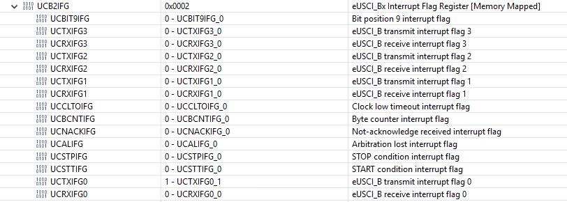
UCB2IFG &= ~(UCTXIFG + UCRXIFG); // Clear any pending interrupts 
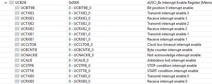
UCB2IE &= ~UCRXIE; // Disable RX interrupt UCB2IE |= UCTXIE; // Enable TX interrupt UCB2CTLW0 |= UCTR + UCTXSTT; // I2C TX, start condition __bis_SR_register(LPM0_bits + GIE); // Enter LPM0 w/ interrupts return MasterModeI2C; } #if defined(__TI_COMPILER_VERSION__) || defined(__IAR_SYSTEMS_ICC__) #pragma vector = USCI_B2_VECTOR __interrupt void USCI_B2_ISR(void) #elif defined(__GNUC__) void __attribute__ ((interrupt(USCI_B2_VECTOR))) USCI_B2_ISR (void) #else #error Compiler not supported! #endif { //Must read from UCB2RXBUF uint8_t rx_val = 0; switch(__even_in_range(UCB2IV, USCI_I2C_UCBIT9IFG)) { case USCI_NONE: break; // Vector 0: No interrupts case USCI_I2C_UCALIFG: break; // Vector 2: ALIFG case USCI_I2C_UCNACKIFG: // Vector 4: NACKIFG UCB2CTLW0 |= UCTXSTP; // stop I2C UCB2CTLW0 &= ~UCTXNACK; // clear interrupt flag // UCB2IFG &= ~UCNACKIFG; // clear interrupt flag. // UCB2CTLW0 |= UCTXSTT; // start after stop break; case USCI_I2C_UCSTTIFG: break; // Vector 6: STTIFG case USCI_I2C_UCSTPIFG: break; // Vector 8: STPIFG case USCI_I2C_UCRXIFG3: break; // Vector 10: RXIFG3 case USCI_I2C_UCTXIFG3: break; // Vector 12: TXIFG3 case USCI_I2C_UCRXIFG2: break; // Vector 14: RXIFG2 case USCI_I2C_UCTXIFG2: break; // Vector 16: TXIFG2 case USCI_I2C_UCRXIFG1: break; // Vector 18: RXIFG1 case USCI_I2C_UCTXIFG1: break; // Vector 20: TXIFG1 case USCI_I2C_UCRXIFG0: // Vector 22: RXIFG0 rx_val = UCB2RXBUF; if (RXByteCtrI2C) { ReceiveBufferI2C[ReceiveIndexI2C++] = rx_val; RXByteCtrI2C--; } if (RXByteCtrI2C == 1) { UCB2CTLW0 |= UCTXSTP; } else if (RXByteCtrI2C == 0) { UCB2IE &= ~UCRXIE; // UCB2CTLW0 |= UCTXSTP; // Send stop condition MasterModeI2C = IDLE_MODE; __bic_SR_register_on_exit(LPM0_bits); // Exit LPM0 } break; case USCI_I2C_UCTXIFG0: // Vector 24: TXIFG0 switch (MasterModeI2C) { case TX_REG_ADDRESS_MODE: UCB2TXBUF = TransmitRegAddr; // UCB2TXBUF = SLAVE_ADDR; if (RXByteCtrI2C) MasterModeI2C = SWITCH_TO_RX_MODE; // Need to start receiving now else MasterModeI2C = TX_DATA_MODE; // Continue to transmision with the data in Transmit Buffer break; case SWITCH_TO_RX_MODE: UCB2IE |= UCRXIE; // Enable RX interrupt UCB2IE &= ~UCTXIE; // Disable TX interrupt UCB2CTLW0 &= ~UCTR; // Switch to receiver MasterModeI2C = RX_DATA_MODE; // State state is to receive data UCB2CTLW0 |= UCTXSTT; // Send repeated start if (RXByteCtrI2C == 1) { //Must send stop since this is the N-1 byte while((UCB2CTLW0 & UCTXSTT)); UCB2CTLW0 |= UCTXSTP; // Send stop condition } break; case TX_DATA_MODE: if (TXByteCtrI2C) { UCB2TXBUF = TransmitBufferI2C[TransmitIndexI2C++]; TXByteCtrI2C--; } else { //Done with transmission UCB2CTLW0 |= UCTXSTP; // Send stop condition MasterModeI2C = IDLE_MODE; UCB2IE &= ~UCTXIE; // disable TX interrupt __bic_SR_register_on_exit(CPUOFF); // Exit LPM0 } break; default: __no_operation(); break; } break; default: break; } }
It sounds like you want a timeout mechanism.
Pick an unused Timer, and set it to interrupt periodically (e.g. 1ms or 10ms). A simple approach is to have it wake up (LPM0_EXIT;) main, and have main decide whether it has been sleeping "too long".
Another approach is to have the ISR count down a global counter -- set by main() before starting the operation -- and when it gets to 0 set a (different) "timeout" global variable and wake up main(). When the transaction completes, set the variable to 0 to avoid "false alarms".
If the I2C transaction times out, you should probably reset (UCSWRST) the USCI device.
Hi Bruce,
I appreciate your response. The problem is as long as my debugger is attached, my all peripherals works properly along with my I2C communication with a slave. The problem arises when I detach my debugger and then power on my device. Everything seems to hang. I somehow found out that my control remains on __bis_SR_register(LPM0_bits + GIE) hanging. I unterstand your approach to come out of LPM by LPM0_EXIT. My Question is what if I2C never works. I always have to jump out of LPM through my timmer. Is there no other way to trigger I2C interrupt execpt going to LPM.
Thank you alot.
The short answer is that you don't need to be in LPM for interrupts to happen. If (as you mentioned) you set GIE up at the top of your program, they can happen any time during the execution of your other code. (Strictly speaking, you don't even need the "+GIE" part, but it's not a bad habit to get into.)
In fact, based on your description, I'm wondering if you're encountering a race in which your I2C operation completes before you go into LPM, and as a result there's no stimulus left (since the wakeup happened a "long time" ago) to wake your main() program up. (The debugger typically affects your program's timing.)
What you should probably add is a global flag e.g. "I2C_Done", which is set by the ISR as part of wakeup and checked by main() before (and after) going into LPM. This is a good idea in any case if you have multiple wakeup sources.
Here are two more-detailed discussions of this phenomenon:
https://e2e.ti.com/support/microcontrollers/msp430/f/166/p/820313/3034992
https://e2e.ti.com/support/microcontrollers/msp430/f/166/p/812166/3005524
Hi Bruce, I appreciate your apt Response. I have tried the Suggestion you have stated in your message to come out of LPM0_Exit after a time interval. The Problem is as I feard earlier. I am able to bring back device in life that means all other peripherals works properly, however my I2C communication don't really work at all. I am unable to receive data from my slave, which in fact works perfectly as Long as Debugger is attached. Do you have any clue, where I am lagging or what is going wrong?
What do you mean by your sentence "I'm wondering if you're encountering a race in which your I2C operation completes before you go into LPM."
Would it help me if I sets the flag as you mentioned "I2C_Done"?
If yes what would be the correct way to do it. In my ISR, would I set a flag as "I2C_Done = 1" and in my maine function back to "I2c_Done=0"?
I have attatched my Registers configurations, if that could tell anything.
Thanks a lot.
// Timer0_A0 interrupt service routine #if defined(__TI_COMPILER_VERSION__) || defined(__IAR_SYSTEMS_ICC__) #pragma vector = TIMER0_A0_VECTOR __interrupt void Timer0_A0_ISR(void) #elif defined(__GNUC__) void __attribute__ ((interrupt(TIMER0_A0_VECTOR))) Timer0_A0_ISR (void) #else #error Compiler not supported! #endif { s_scheduler.timer++; if (!(s_scheduler.timer % 4)) { s_scheduler.serve_display = 1; ReadandProcessRTCValues(); } if (!(s_scheduler.timer % 9)) { s_scheduler.serve_h = 1; } if (!(s_scheduler.timer % 10)) { LPM0_EXIT; UCB2CTLW0 = UCSWRST; } s_scheduler.timer = 0; }
What I see here is that UCSWRST is still set. Based on a single snapshot, this could be cause (issuing an STT while the I2C is in reset) or effect (the STT got "stuck" and UCSWRST was set due to timeout). Stating the obvious: Once a timeout has set UCSWRST, someone needs to clear it before the next operation.
Re-reading your code, "(MasterModeI2C==IDLE_MODE)" is probably a suitable substitute for my suggested "I2C_Done" flag. Are you checking the ReadReg() return value?
Are "I2C done" and "I2C Timeout" the only wakeup sources, or are there other cases (not shown) where e.g. the timer ISR might do a wakeup?
Hi Bruce,
I appreciate your Response. UCSWRST is enabled, because I was Setting it again and again every 10ms in my Timer Routine along with LPM0_exit. If I comment it in my Timer Routine. The UCSWRST value in Register section Shows to 0.
I have debugged it in steps and find out MasterModeI2C = TX_REG_ADDRESS_MODE, which it has to be once I call ReadReg(). However once I step Forward into ReadReg() to jump into my ISR, it remains stranded on __bis_SR_register(LPM0_bits + GIE). I have added break points in my ISR everywhere. It ain't coming not even a single time in my ISR. That's the reason it gets stuck there and Nothing works.
I'll appreciate your Response.
Thanks
This set of symptoms (stalled in TX mode) sounds like a NACK from the slave.
I expect your code is using the same address in both cases, so my next guess is timing. Are you power-cycling your MCU after disconnecting the debugger? if so, does that power-cycle the slave device as well? I wonder if the slave is just being slow to start up, and then the failures cascade. (Keep in mind that a NACK is really the absence of an ACK, i.e. if the slave does nothing then that constitutes a NACK.)
A quick experiment would be to try a Reset of the MCU without power-cycling.
Hi Bruce,
once again, I appreciate your Response. I didn't really comprehend the idea of power Cycling you refered to. I am Burning program into MSP-Chip through Debugger. If I switch off and on as Long as Debugger is connected it works somwhow. If I detach the Debugger it doesn't work after switching off and on.
To make Things easier I have eleminated all the peripherals from my Project except I2c and a timer and connected it to Osci to have a feel About the Signal Transmission. It seems to work properly. I debugged it and I was surprise to see that I am not hanging where I was. I even exclude __bis_SR_register(LPM0_bits + GIE) from my Code, which I till now though is mandatory to trigger the Interrupt. It worked, I think __bis_SR_register(LPM0_bits + GIE) is only optional.
If I add all my peripherals then it stops and doesn't work, do you think there is a Hardware Problem that my slave ain't get enough current to process Signals from my MSP? If the Debugger is attached, it somehow get extra current from Debugger and works?
I appreciate your Response.
thanks
If removing the code for all your other devices causes the I2C to function properly, the first guess is that one of the other devices is interfering.
Try re-adding the other code one device at a time.
Hi Bruce,
I appreciate your Response. I have measured it wit Osci. Osci is showing me only two straight lines, that means MSP is not even sending the slave address which it Needs to do before going into ISR. If my Debugger is attached, I see all the data Transfer on my OSCI. I thought slave is not reponding on my querry. It's however other way round. Do you find any logic in it?
I appreciate your reponse.
Thanks,
What is your other code (not shown) doing? Maybe your program is not even reaching the ReadReg call.
When you generate the I2C start condition there are a couple of error conditions that could occur which have their own interrupts. You could lose arbitration or the device might not acknowledge its address. I see code in the ISR for the NACK case but I do not see where that interrupt is enabled in UCB2IE.
Hi Bruce,
I appreciate your response. I have kind of a display attached to it, I have added a simple counter to see if it goes in. It goes in the function Readreg and the counter adds up every time the function is being called. However it doesn't count up once I add the counter in my ISR. so my function is being called however it's not going into my ISR. Since my function is being called, and not showing any fluctuation on OSCI and not going into ISR. The start condition doesn't work without debugger.
Thanks a lot
Hi David,
I appreciate your response. I am using the TI example with some modification to suit my need. NACK interrupt is being enabled in the initialisation routine of I2C. I am seeing no fluctuation in the signal not even start condition or sending the address, which it needs to do before going to ISR. Only dead straight SDA and SCL signals. It changes completely, if debugger is attached. Then I see whole communication and data.
void initI2C() { UCB2CTLW0 = UCSWRST; // Enable SW reset UCB2CTLW0 |= UCMODE_3 | UCMST | UCSSEL__SMCLK | UCSYNC; // I2C master mode, SMCLK UCB2BRW = 160; // fSCL = SMCLK/160 = ~100kHz UCB2I2CSA = SLAVE_ADDR; // Slave Address UCB2CTLW0 &= ~UCSWRST; // Clear SW reset, resume operation UCB2IE |= UCNACKIE; }
One other thing to try.
I looked at my I2C code and after initializing, I check to see if the bus is busy (UCBBUSY) and if it is, try to clear it by generating a clock by brute force. I can't find anything in my notes explaining why I did that...
Hi David,
I appreciate your response. I can try your suggestion. How are you generating a clock by brute force? As far as I understand, the processor generates clock once it see there would be need for it. On SPI, we keep sending dummy bytes to keep generating clock, however it's not the case with I2C. Do you have me a example?
I'll appreciate your response.
I take over the pin. This is for a different part so the details aren't the same:
/* Check to see if the bus is busy. If it is, attempt to clear the bus by generating a clock manually. */ if (UCB0STAT & UCBBUSY) { P3DIR &= ~BIT2; P3SEL &= ~BIT2; P3OUT &= ~BIT2; P3DIR |= BIT2; P3SEL |= BIT1 + BIT2; }
This is probably a stupid question but, do you have appropriate pullups on the I2C bus even without a slave attached?
Hey David,
I appreciate your reply. Just to understand the logic, are you configuring your SCL multiplexed pin to gpio and generating a output signla onto it, once you find out that bus is busy?
Yes the pullups are there, the same ciruitry is being used with beaglebone and it works with no errors. Only in combination with MSP, it ain't working.
thanks a lot and have a nice weekend.
That was all of the code. Reconfigure the pin to GPIO, force a clock transition, and then return the pin to I2C. This might help out if a slave was stuck but is of little help otherwise.
But I don't think I ever tried my code without a slave attached. Assuming that everything works fine with the slave attached, what happens if you use the wrong address?
Looking at my notes, I2C gave me fits at first. So much so that I resorted to some bit banged I2C code just to make sure it wasn't the slave. (a MPU-9150)
Hi David,
once again, I appreciate your Response. I have somehow find out, what was the root cause. Actually I was initialising I2C first and then my normal GPIOs. After initializing GPIOs, one hast to disable
PM5CTL0. This was actually the Problem, if I initialize GPIOs first and then configure my I2C, everything works perfekt. I couldn't find out from data sheet, do you have any idea what actually the sequece should be for initialization? It can't be random. Isn't it?
thanks a lot
Section 10.3.1 of the guide describes what to do coming out of reset. It isn't clear but it is possible that altering the PxSEL registers with LOCKLPM5 set might not work.
I always give the GPIOs a generic config (PxDIR and PxOUT) first thing after disabling the watchdog and then clear the lock bit. Later initialization code will then change that as required.
Hi David,
I appreciate your Response and extend my gratitude for your Kind help. Now I am doing like this.
thanks a lot
// Hardware Initialization initClock(); initGPIO(); init_SCI_A1(); init_SCI_A0(); init_scheduler(); S_UART_SPI(2, 1); init_timer_a0(); init_timer_a1(); init_ADC(); initSPI(); initI2C(); __bis_SR_register(GIE); // Data initialization initData();
**Attention** This is a public forum