


Hello, and thank you for taking the time to read my issue.
I've written a program that is using both timer B0 and the RTC. While the main body is active, the B0 timer is suppose just flashing an led at 1 sec intervals. I threw in a while loop to hold the system active for 10 seconds. After it exits the hold, it will then disable timer_B0, and enable the RTC. I then enable low power mode and it sleeps for 11 seconds. Once it exits low power mode, the RTC is disabled and the Timer_B0 is re-enabled. and it repeats.
#include <msp430.h>

void initGpio(void);

unsigned int iiiii;
unsigned int my_seconds;

int main(void)
{
    WDTCTL = WDTPW | WDTHOLD;                    // Stop WDT
    my_seconds = 0;

    initGpio();                             // Configure GPIO

    // Initialize XT1 32kHz crystal
    P2SEL1 |= BIT6 | BIT7;                  // P2.6~P2.7: crystal pins
    do
    {
        CSCTL7 &= ~(XT1OFFG | DCOFFG);      // Clear XT1 and DCO fault flag
        SFRIFG1 &= ~OFIFG;
    } while (SFRIFG1 & OFIFG);              // Test oscillator fault flag

    __enable_interrupt();               // The RTC interrupt should trigger now...

    RTCMOD = (10*32)-1;
    RTCCTL = RTCSS_2 | RTCSR | RTCPS_7;

    // Configure Timer_A
    TB0CTL = TBSSEL_1 | CNTL_1 | MC_2 | ID_3 | TBCLR | TBIE;      // ACLK, count mode, clear TBR, enable interrupt

    while(1)
        {

            iiiii = 0;

            while (iiiii < 10)
            {}

            TB0CTL &= ~TBIE;
            P1OUT &= ~BIT0;
            RTCCTL |= RTCSR | RTCIE;
            P6OUT &= ~BIT6;
            _bis_SR_register(LPM3_bits| GIE);
            RTCCTL &= ~RTCIE;
            TB0CTL |= TBIE | TBCLR;
        }
}

void initGpio(void)
{
    P1DIR = 0xFF; P2DIR = 0xFF; P6DIR = 0xFF;
    P1REN = 0xFF; P2REN = 0xFF;
    P1OUT = 0x00; P2OUT = 0x00; P6OUT = 0x00;

    // Configure GPIO
        P1DIR |= BIT0;
        P1OUT |= BIT0;
        P6DIR |= BIT6;
        P6OUT |= BIT6;

    // Disable the GPIO power-on default high-impedance mode
    // to activate previously configured port settings
    PM5CTL0 &= ~LOCKLPM5;
}

// Timer0_B3 Interrupt Vector (TBIV) handler
#if defined(__TI_COMPILER_VERSION__) || defined(__IAR_SYSTEMS_ICC__)
#pragma vector=TIMER0_B1_VECTOR
__interrupt void TIMER0_B1_ISR(void)
#elif defined(__GNUC__)
void __attribute__ ((interrupt(TIMER0_B1_VECTOR))) TIMER0_B1_ISR (void)
#else
#error Compiler not supported!
#endif
{
    switch(__even_in_range(TB0IV,TB0IV_TBIFG))
    {
        case TB0IV_NONE:
            break;                               // No interrupt
        case TB0IV_TBCCR1:
            break;                               // CCR1 not used
        case TB0IV_TBCCR2:
            break;                               // CCR2 not used
        case TB0IV_TBIFG:
            P1OUT ^= BIT0;                       // overflow
            iiiii++;
            my_seconds++;
            break;
        default:
            break;
    }
}

#if defined(__TI_COMPILER_VERSION__) || defined(__IAR_SYSTEMS_ICC__)
#pragma vector = RTC_VECTOR
__interrupt void RTC_ISR(void)
#elif defined(__GNUC__)
void __attribute__ ((interrupt(RTC_VECTOR))) RTC_ISR (void)
#else
#error Compiler not supported!
#endif
{
    switch(__even_in_range(RTCIV, RTCIV_RTCIF))
    {
        case RTCIV_NONE : break;            // No interrupt pending
        case RTCIV_RTCIF:                   // RTC Overflow
            // Toggle LED on P1.0
            P6OUT ^= BIT6;
            //TB0CTL ^= TBIE;

            // Store P1OUT value in backup memory register
            *(unsigned int *)BKMEM_BASE = P1OUT;
            _low_power_mode_off_on_exit();
            break;
        default:          break;
    }
}
Here is the issue, the above code was just my test for implementing the dual timer, enable disable process. I've moved over the code to my actual program and what I'm seeing is after I exit the low power mode the first time, which works correct, my system re-enables timer_b0 and counts just fine, but when its time to enter lowpowermode, it jumps immediately to the ISR. No delay.
I checked the registers, and RTCMOD is still showing 15F (351 or 11 seconds). There is no difference between the registers before and after the first time it enters lpm.
before first LPM
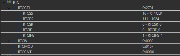
after first lpm

