This thread has been locked.

If you have a related question, please click the "Ask a related question" button in the top right corner. The newly created question will be automatically linked to this question.

CCS/MSP432P401R: Timer UP MODE

Part Number: MSP432P401R


Tool/software: Code Composer Studio

Dear team,

I am using MSP432P401R LAUNCHPAD(red) and the following code

http://dev.ti.com/tirex/explore/node?node=ALCJfiYhvUNkK-GgDpvrCw__z-lQYNj__LATEST 

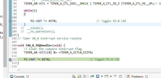
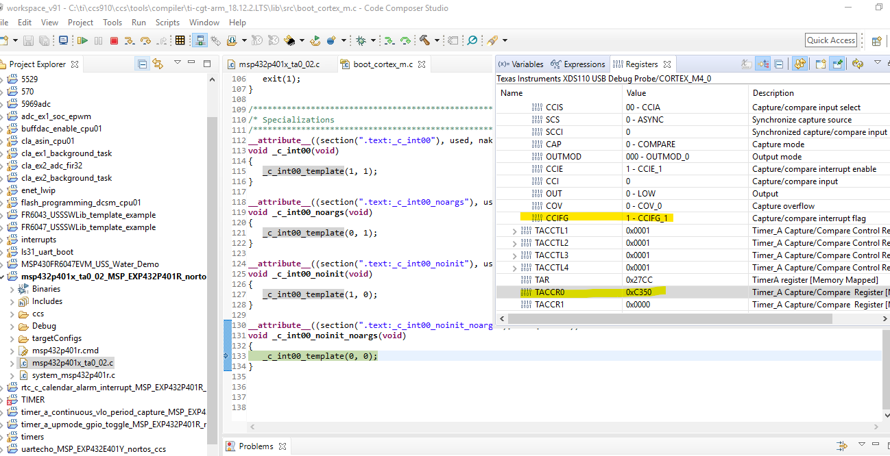
I used CCS to debug it and i found that the TAxCCR0 could not go to zero after it reached 50000. The TIMER_A_CCTLN_CCIFG always be 1 (could not be clear) .

Besides i always enter "_c_int00_noinit_noargs"

Please help.

BR,

Susan

  • 1) TA0CCR0 doesn't reset to 0 on a EQU0 compare match, rather TA0R does

    2) The CCIFG appears to be always-on since SMCLK continues to count during a breakpoint. I'm pretty sure there's a check-box to make it not do that, but I wasn't able to find it just now. If you add ID=3 to the configuration, you'll be able to see the LED blink, which demonstrates that the ISR is resetting CCIFG:

    >TIMER_A0->CTL = TIMER_A_CTL_SSEL__SMCLK | TIMER_A_CTL_ID_3 |TIMER_A_CTL_MC__UP;// SMCLK, UP mode

    3) I suspect your traceback to c_init is also a debugger illusion, since it can't figure out the traceback from an ISR. (I didn't see it just now, but I have seen it in the past.)

  • Thanks!

    The following is my code. I could not reach 

     P2->OUT ^= BIT0;                        // Toggle P2.0 LED

    Please help

    /* --COPYRIGHT--,BSD_EX
     * Copyright (c) 2013, Texas Instruments Incorporated
     * All rights reserved.
     *
     * Redistribution and use in source and binary forms, with or without
     * modification, are permitted provided that the following conditions
     * are met:
     *
     * *  Redistributions of source code must retain the above copyright
     *    notice, this list of conditions and the following disclaimer.
     *
     * *  Redistributions in binary form must reproduce the above copyright
     *    notice, this list of conditions and the following disclaimer in the
     *    documentation and/or other materials provided with the distribution.
     *
     * *  Neither the name of Texas Instruments Incorporated nor the names of
     *    its contributors may be used to endorse or promote products derived
     *    from this software without specific prior written permission.
     *
     * THIS SOFTWARE IS PROVIDED BY THE COPYRIGHT HOLDERS AND CONTRIBUTORS "AS IS"
     * AND ANY EXPRESS OR IMPLIED WARRANTIES, INCLUDING, BUT NOT LIMITED TO,
     * THE IMPLIED WARRANTIES OF MERCHANTABILITY AND FITNESS FOR A PARTICULAR
     * PURPOSE ARE DISCLAIMED. IN NO EVENT SHALL THE COPYRIGHT OWNER OR
     * CONTRIBUTORS BE LIABLE FOR ANY DIRECT, INDIRECT, INCIDENTAL, SPECIAL,
     * EXEMPLARY, OR CONSEQUENTIAL DAMAGES (INCLUDING, BUT NOT LIMITED TO,
     * PROCUREMENT OF SUBSTITUTE GOODS OR SERVICES; LOSS OF USE, DATA, OR PROFITS;
     * OR BUSINESS INTERRUPTION) HOWEVER CAUSED AND ON ANY THEORY OF LIABILITY,
     * WHETHER IN CONTRACT, STRICT LIABILITY, OR TORT (INCLUDING NEGLIGENCE OR
     * OTHERWISE) ARISING IN ANY WAY OUT OF THE USE OF THIS SOFTWARE,
     * EVEN IF ADVISED OF THE POSSIBILITY OF SUCH DAMAGE.
     *
     *******************************************************************************
     *
     *                       MSP432 CODE EXAMPLE DISCLAIMER
     *
     * MSP432 code examples are self-contained low-level programs that typically
     * demonstrate a single peripheral function or device feature in a highly
     * concise manner. For this the code may rely on the device's power-on default
     * register values and settings such as the clock configuration and care must
     * be taken when combining code from several examples to avoid potential side
     * effects. Also see www.ti.com/.../mspdriverlib for an API functional
     * library & https://dev.ti.com/pinmux/ for a GUI approach to peripheral configuration.
     *
     * --/COPYRIGHT--*/
    //******************************************************************************
    //  MSP432P401 Demo - Timer0_A3, Toggle P1.0, CCR0 Up Mode ISR, DCO SMCLK
    //
    //  Description: Toggle P1.0 using software and TA_0 ISR. Timer0_A is
    //  configured for up mode, thus the timer overflows when TAR counts
    //  to CCR0. In this example, CCR0 is loaded with 50000.
    //  ACLK = n/a, MCLK = SMCLK = TACLK = default DCO ~3MHz
    //
    //
    //           MSP432P401x
    //         ---------------
    //     /|\|               |
    //      | |               |
    //      --|RST            |
    //        |               |
    //        |           P1.0|-->LED
    //
    //
    //   William Goh
    //   Texas Instruments Inc.
    //   Oct 2016 (updated) | November 2013 (created)
    //   Built with CCSv6.1, IAR, Keil, GCC
    //******************************************************************************
    #include "ti/devices/msp432p4xx/inc/msp.h"
    
    int main(void) {
        WDT_A->CTL = WDT_A_CTL_PW |             // Stop WDT
                WDT_A_CTL_HOLD;
    
        // Configure GPIO
        P1->DIR |= BIT0;
        P1->OUT |= BIT0;
    
        P2->DIR |= BIT0;
        P2->OUT |= BIT0;
    
        SCB->SCR |= SCB_SCR_SLEEPONEXIT_Msk;    // Enable sleep on exit from ISR
    
        // Ensures SLEEPONEXIT takes effect immediately
        __DSB();
    
        // Enable global interrupt
        __enable_irq();
    
        NVIC->ISER[0] = 1 << ((TA0_0_IRQn) & 31);
    
        TIMER_A0->CCTL[0] &= ~TIMER_A_CCTLN_CCIFG;
        TIMER_A0->CCTL[0] = TIMER_A_CCTLN_CCIE; // TACCR0 interrupt enabled
        TIMER_A0->CCR[0] = 50000;
       // TIMER_A0->CTL = TIMER_A_CTL_SSEL__SMCLK | // SMCLK, UP mode
             //   TIMER_A_CTL_MC__UP;
        TIMER_A0->CTL = TIMER_A_CTL_SSEL__SMCLK | TIMER_A_CTL_ID_3 |TIMER_A_CTL_MC__UP;// SMCLK, UP mode
    
        while(1)
        {
    
            P2->OUT ^= BIT0;                        // Toggle P2.0 LED
        }
      //  __sleep();
      //  __no_operation();
    }
    // Timer A0_0 interrupt service routine
    
    void TA0_0_IRQHandler(void) {
        // Clear the compare interrupt flag
        TIMER_A0->CCTL[0] &= ~TIMER_A_CCTLN_CCIFG;
    
        P1->OUT ^= BIT0;                        // Toggle P1.0 LED
    }
    

  • Hi Susan,

    TACCR0 is a compare register you write a value to and TAR counts to that value. This is why you are always seeing 5000 in TACCR0. All of this information and more on Timer A can be read in Chapter 19 of the MSP432 Technical Reference Manual

    The interrupt controller automatically clears the interrupt flag as soon as it enters the ISR.

    I believe you are entering "_c_int00_noinit_noargs" due to a side effect of breaking the code execution inside the ISR in debug mode.

    Hope this helps,

    Seong

  • Thanks

    I still feel confused.

    Why I could not reach 

     P2->OUT ^= BIT0;                        // Toggle P2.0 LED

  • >   SCB->SCR |= SCB_SCR_SLEEPONEXIT_Msk;    // Enable sleep on exit from ISR

    This is causing main to stop forever (after the first interrupt). I recommend you remove it. It wasn't wrong with the original code, but with your change now it's wrong.

  • > The interrupt controller automatically clears the interrupt flag as soon as it enters the ISR.

    I hesitate to disagree with Seong Kim, but this is not the case for the MSP432 TimerA. It is true for the MSP430 TimerA.

    [Edit: Changed "was" to "is" since the MSP430 still, um, "is".]

**Attention** This is a public forum