


Part Number: MSP430FR2633
Other Parts Discussed in Thread: HDC2010
I'm using the Driver Library's I2C Master Tx Single example to transmit on our I2C bus. I have modified the example to remove the clock initializations (as they're already confirmed correct in the CAPT_BSP), and switch the GPIO_setAsPeripheralModuleFunctionInputPin() to the correct port for the 2633. I have also added a call to EUSCI_B_I2C_isBusBusy() before the transmit The call to EUSCI_B_I2C_masterSendSingleByte() is not returning.
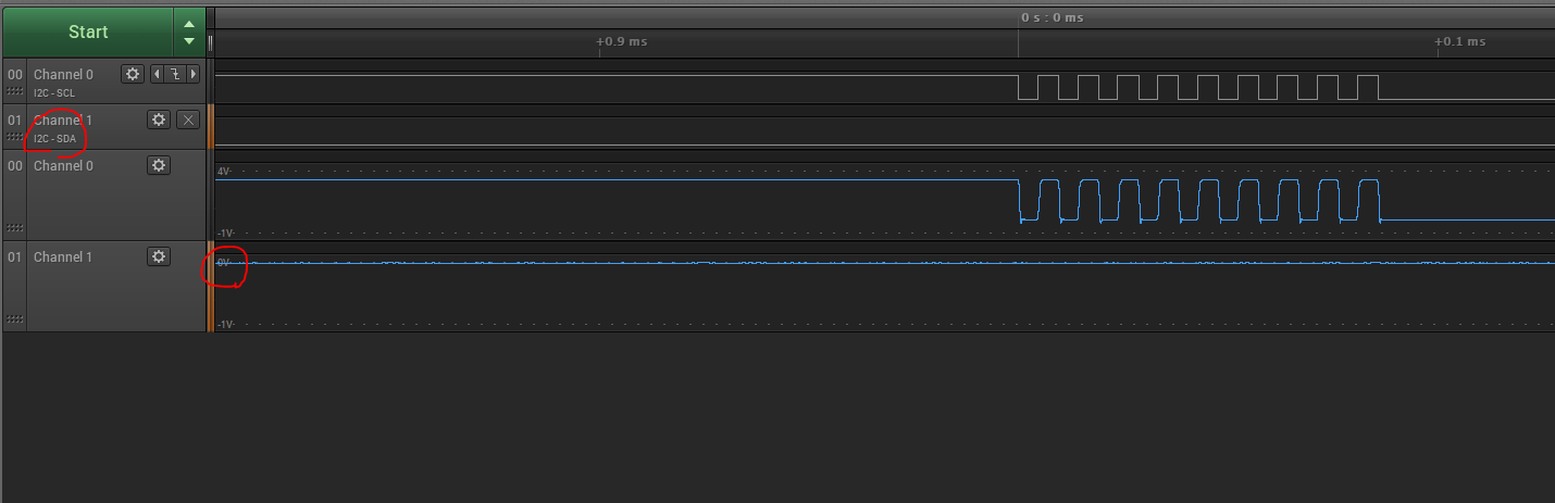
Looking at the bus, I am seeing clocks when the transfer is initiated. However, SDA is staying low so we're not getting a start condition and not seeing any data.
I've confirmed our pullups are placed (3.3k) and ohmed out he connection to one of the slaves.
Code:
WDT_A_hold(WDT_A_BASE);
// //Set Ratio and Desired MCLK Frequency and initialize DCO
// CS_initFLLSettle(
// CS_SMCLK_DESIRED_FREQUENCY_IN_KHZ,
// CS_SMCLK_FLLREF_RATIO
// );
//
// //Set SMCLK = DCO with frequency divider of 1
// CS_initClockSignal(
// CS_SMCLK,
// CS_DCOCLKDIV_SELECT,
// CS_CLOCK_DIVIDER_1
// );
//
// //Set MCLK = DCO with frequency divider of 1
// CS_initClockSignal(
// CS_MCLK,
// CS_DCOCLKDIV_SELECT,
// CS_CLOCK_DIVIDER_1
// );
//
// Configure Pins for I2C
/*
* Select Port 5
* Set Pin 2, 3 to input with function, (UCB0SIMO/UCB0SDA, UCB0SOMI/UCB0SCL).
*/
GPIO_setAsPeripheralModuleFunctionInputPin(
GPIO_PORT_P1,
GPIO_PIN2 + GPIO_PIN3,
GPIO_PRIMARY_MODULE_FUNCTION
);
/*
* Disable the GPIO power-on default high-impedance mode to activate
* previously configured port settings
*/
PMM_unlockLPM5();
//Initialize transmit data packet
transmitData = 0x01;
//Initialize Master
EUSCI_B_I2C_initMasterParam param = {0};
param.selectClockSource = EUSCI_B_I2C_CLOCKSOURCE_SMCLK;
param.i2cClk = CS_getSMCLK();
param.dataRate = EUSCI_B_I2C_SET_DATA_RATE_400KBPS;
param.byteCounterThreshold = 1;
param.autoSTOPGeneration = EUSCI_B_I2C_NO_AUTO_STOP;
EUSCI_B_I2C_initMaster(EUSCI_B0_BASE, ¶m);
//Specify slave address
EUSCI_B_I2C_setSlaveAddress(EUSCI_B0_BASE,
HW_ENV_SLAVE_ADDR
);
//Set in transmit mode
EUSCI_B_I2C_setMode(EUSCI_B0_BASE,
EUSCI_B_I2C_TRANSMIT_MODE
);
//Enable I2C Module to start operations
EUSCI_B_I2C_enable(EUSCI_B0_BASE);
while (1)
{
while (EUSCI_B_I2C_isBusBusy(EUSCI_B0_BASE)) ;
//Send single byte data.
EUSCI_B_I2C_masterSendSingleByte(EUSCI_B0_BASE,
transmitData
);
//Delay until transmission completes
while (EUSCI_B_I2C_isBusBusy(EUSCI_B0_BASE)) ;
//Delay between each transaction
__delay_cycles(50);
//Increment transmit data counter
transmitData++;
}

