This thread has been locked.

If you have a related question, please click the "Ask a related question" button in the top right corner. The newly created question will be automatically linked to this question.

EVM430-FR6047: I2C communication error

Part Number: EVM430-FR6047


I would like to be able to communicate with fr6047 directly using i2c. I have connected my i2c master to comm_sda and comm_scl. I have connected 3V3 to external power. All jumpers are taken off (except J32) and the power select is set to external.
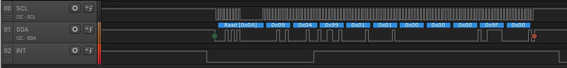
But when I send a command, e.g. h55, hAA, h09, h04, h99, h00, h00, h00, h00, h00, h9D, h00, to get version etc. I do not get the required answer back, only a message that no piezo is connected. No matter what command I send to fr6047, I get that message back.
Is there anything I overlooked regarding i2c communication with fr6047?

  • Hello,

    I need to look into this further.  In the USS Design Center User Guide, we have some details on the communications protocol, but the commands you mention are not shown.  I will dig into this and provide some feedback shortly.  You can find the users guide at the directory below if you installed to the default directory.

    C:\ti\msp\USS_02_20_00_18\USS\docs 

  • Hello,

    I took some I2C logic analyzer captures with the EVM connected to the GUI.  I do receive the correct response to the 0x99 command.  If I do not have a pipe connected to the EVM, I am also seeing the error packet as you have seen.  The response to the 0x99 command is only sent after the measurement is made, so this may take 1sec if that is the measurement interval you have set.  See the captures below.  I think the problem is that you are seeing the error packet before you are receiving the response to 0x99 and your packet handler is not taking care of the response to the 0x99 request. 

  • Thank you very much for your response.
    I have done the same analysis and come to the same conclusion.
    But I can see in your pictures that you have an interrupt line attached (comm_irq I suppose). is that correctly understood that I only can read answers when interrupt line goes low?
    I will try to see if I can get some more useful answers if I implement it with interrupts.

  • Correct, the interrupt line can be used to indicate when new data is available.

  • perfect, thank you.

    Now I have communication between raspberry pi and fr6047.

    The documentation describes the command library. But there is very little about how to read the i2c responses.
    Is there any documentation of the responses?

    for example, when I send a query on 'UPS and DNS captures' (0x98), I get some packets back, including all the measurement points, but I can't find the documentation on how to read these packages. I can easily read the measurement points, but the packages that come before and after the measurement points must describe something about it, but what?

    An example:

    Start, h14 [ h0A | WR ], h55, hAA, h09, h04, h98, h01, h01, h00, h00, h00, h9E, h00, Stop (request UPS and DNS capture)
    Start, h15 [ h0A | RD ], h0D, h04, hB4, h01, h01, h06, h75, hFA, h6C, hFA, h64, hFA, hF3, h04 NAK, Stop (something to describe the measurement points of UPS ????)
    ..
    A lot of measurement points
    ..
    Start, h15 [ h0A | RD ], h0D, h04, hB4, h01, h00, h06, hEC, hFF, hEB, hFF, hEA, hFF, h7D, h06 NAK, Stop (something to describe that the measurement has stopped ????)

    Start, h15 [ h0A | RD ], h0D, h04, hB5, h01, h01, h06, hEC, hFF, hEB, hFF, hEA, hFF, h7F, h06 NAK, Stop (something to describe the measurement points of DNS ????)
    ..
    A lot of measurement points
    ..
    Start, h15 [ h0A | RD ], h0D, h04, hB5, h01, h00, h06, h6C, hFA, h63, hFA, h5A, hFA, hD7, h04 NAK, Stop (something to describe that the measurement has stopped ????)

    The documentation describes the command request like this:

  • This is described with the plotting parameters description section in the users guide.  In the case of the 0x98 command, you should first receive a 0xB4 which identifies the number of packets and indicate start of UPS transmission.  The next packet should be a 0xC0 which contains the UPS payload data, then a 0xB4 indicating the transmission of UPS is complete.  The DNS transmission is similar, but uses 0xC1 and 0xB5 commands.   

**Attention** This is a public forum