This thread has been locked.

If you have a related question, please click the "Ask a related question" button in the top right corner. The newly created question will be automatically linked to this question.

CCS/MSP430F5438A: msp430f5438a

Part Number: MSP430F5438A

Tool/software: Code Composer Studio

Hi,

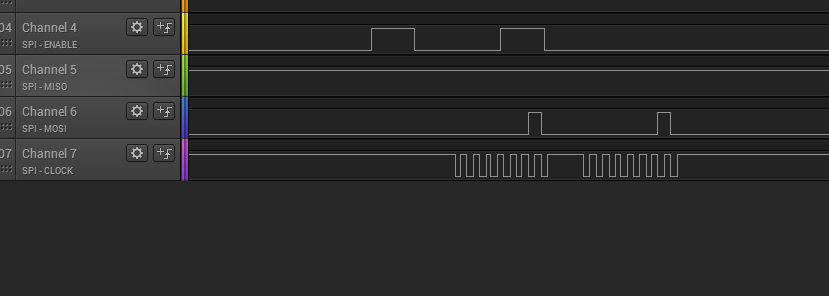
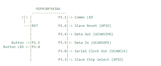
i m trying to integrate msp430f5438a & winbond spi flash ic via spi communication. i m facing problems in transmitting data from master(msp430f5438a) to slave select. i think i m doing mistake in slave selection enable & disable. if i m seeing the signals in logic analyser slave select pin is not syncing with mosi & clock signal. if i disable "Enable" option in logic analyser settings, given data signals are perfectly shown on analyser. 

i have attached my code, please help me where i m doing mistake. also i have attached my logic analyser o/p.

#include "msp430x54xA.h"

unsigned char MST_Data,SLV_Data;

void main(void)
{
WDTCTL = WDTPW+WDTHOLD; // Stop watchdog timer

P1OUT |= 0x02; // Set P1.0,1 for LED

P3OUT |= 0X01; // slave select p3.0
P3DIR |= 0X01;
P1DIR |= 0x03; // Set P1.0,1 to output direction
P3SEL |= 0x0E; // P3.5,4,0 option select

UCB0CTL1 |= UCSWRST; // Put state machine in reset

/* 4 pin spi, master mode, msb first,synchronous comm, clock polarity high */

UCB0CTL0 |= UCMST+UCSYNC+UCMSB+UCCKPL+UCMODE_1 ;

UCB0CTL1 |= UCSSEL_2; // SMCLK
UCB0BR0 = 0x02; // 2
UCB0BR1 = 0;
// UCB0MCTL = 0; // No modulation
UCB0CTL1 &= ~UCSWRST; // **Initialize USCI state machine**
UCB0IE |= UCRXIE; // Enable USCI_A0 RX interrupt

__bis_SR_register(GIE);

MST_Data = 0x02; // Initialize data values
SLV_Data = 0x00;

while(1)
{
P3OUT |= BIT0; // slave select - high
UCB0TXBUF = MST_Data; // Transmit first character
while (!(UCA0IFG&UCTXIFG));
P3OUT &= ~BIT0; // slave select - low

__delay_cycles(5);
}

}


#pragma vector=USCI_B0_VECTOR
__interrupt void USCI_B0_ISR(void)
{
switch(__even_in_range(UCB0IV,4))
{
case 0: break; // Vector 0 - no interrupt
case 2: // Vector 2 - RXIFG
// while (!(UCB0IFG&UCTXIFG)); // USCI_A0 TX buffer ready?

break;
case 4: break; // Vector 4 - TXIFG
default: break;
}
}

  • > while (!(UCA0IFG&UCTXIFG));

    This doesn't wait for the byte to be transmitted, so the chip select happens too early. (It's also the wrong USCI.) Try instead:

    > while (!(UCB0IFG & UCRXIFG)) /*EMPTY*/;  // Wait for byte exchange to complete

    > (void)UCB0RXBUF;  // Clear UCRXIFG for next time

    and remove this line, since the IE will just get in the way:

    > UCB0IE |= UCRXIE; // Enable USCI_A0 RX interrupt

  • Hi, thanks for the reply.

    i have got spi mster & slave communication with 3 wire spi.

    but if i add, 

     while (!(UCB0IFG & UCRXIFG)); line, there is no data transmitt. MOSI line becomes low. 

    now i have to interface winbond spi ic to msp430, for that i must use cs pin to enable the spi flash ic. kindly help me in spi configuration to interface winbond ic. i have attached the winbond ic data sheet.

    w25q64fv revs 07182017.pdf

  • > but if i add,  while (!(UCB0IFG & UCRXIFG)); line, there is no data transmitt. MOSI line becomes low. 

    It sounds like you didn't remove the line that sets UCRXIE. But if you've found a solution, that's fine.

  • Hello,

    I'm glad you got 3 wire SPI communication up and running. Please refer to the TI Resource Explorer for code examples that show how to properly initialize and use the USCI SPI peripheral for 4 wire SPI communication.

    Best regards,

    Matt

  • I have  doubt on your statement. if i remove UCRXIE, then how can i receive the data from slave? i m getting confusion with this. please clarify it.

  • Hi,

    i checked 4 wire spi in ti explorer. it gives me some idea. but in 4 wire communication we need only 4 wires right(Clock, miso, mosi, slave select). but they have configured 5 wires for mater , slave communication. please clarify this.


    Here, what is slave reset is used for ? and what is slave select is used for ? 

    In my spi flash ic, there are clock,DO,DI,CS,VCC,GND, WP pins only available.

  • > if i remove UCRXIE, then how can i receive the data from slave? 

    The code you posted was throwing away the received data, so my replacement code preserved that property.

    If you replace

    > (void)UCB0RXBUF;  // Clear UCRXIFG for next time

    with

    > ReceivedData = UCB0RXBUF;  // Capture slave data and clear UCRXIFG for next time

    you will receive some data.

  • > In my spi flash ic, there are clock,DO,DI,CS,VCC,GND, WP pins only available

    The SPI people came up with a perfectly good, unambiguous nomenclature for these pins, but some manufacturers somehow forgot it:

    SCK: CLK (Serial ClocK)

    MISO: DO (Master In Slave Out)

    MOSI: DI (Master Out Slave In)

    /CS: /CS (Chip Select)

    Your Flash chip doesn't have a slave reset, so don't use that.

    What it does have is /WP and /HOLD, which you need to deal with: There's no mention of internal pullups on these pins (presumably due to the QSPI feature), but they mustn't be allowed to float. If your board doesn't connect these to Vcc, you should connect them to GPIOs and drive them high.

  • I have tried all the above explained scenarios but its not working as mentioned. Kindly send any frame set or example code if any.

    Thank you.

  • I'm not sure which scenarios you're referring to -- I think there's really only one choice above.

    What exactly is "not working"?

    I don't have this equipment (though I've worked with similar devices), so I don't have any example code. Maybe Winbond has some?

  • actual problem is that no response is coming from spi flash ic.

  • This may be an issue that you need to reach out to Winbond about since you are finding that it is the spi flash ic that is not responding to the MSP430 SPI messages.

    -Matt

**Attention** This is a public forum