This thread has been locked.

If you have a related question, please click the "Ask a related question" button in the top right corner. The newly created question will be automatically linked to this question.

CCS/MSP432P401R: Issue with code integration

Part Number: MSP432P401R
Other Parts Discussed in Thread: CC3120, CC3120BOOST

Tool/software: Code Composer Studio

CCS/MSP432P401R: Issue with code integration of bump sensor, tachometer into wifi module Lab 20 in MSP432P401R launchpad and CC3120

Hi

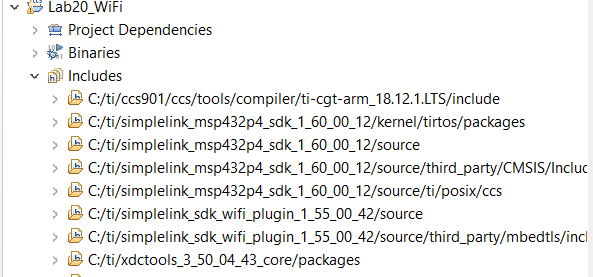
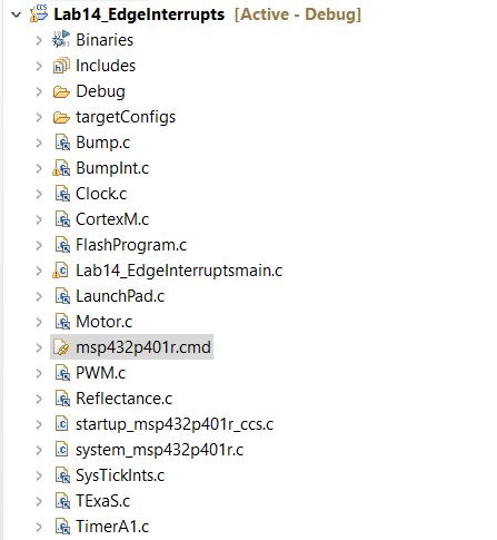
I'm facing some issue when bump sensor and tachometer are integrated into wifi module. Both parts does not work. Pthread is quite confusing in the wifi module and can you show us the way so that I am able to integrate both parts into the wifi module.

  • Hi Myo,

    We will look into this and get back to you shortly.

    BR,

    Seong

  • Hi Myo Min Min Paing,

    You can learn about pthreads here --> http://processors.wiki.ti.com/index.php/SYS/BIOS_POSIX_Thread_%28pthread%29_Support

    Before trying to integrate everything together, I suggest you take one step at a time. Start with the "empty" project from the SDK to get one sensor working. Then get another sensor working on an separate "empty" project. Once this is done, integrate the two to have both sensors working together. You should then try to integrate this with the network_terminal example.

    BR,

    Seong

  • Hi Seong

    Ok thanks a lot. I'm learning about it. At the mean time, may I know whether Posix thread can support timers and interrupts for motors, bump sensor and tachometer same in low latency as in MSP432P401R? It is quite inconvenient to switch the timers and interrupts that have been previously created for those sensors and motors.

    Regards

    Min Min

  • Hi Seong

    When I add bump sensor to the Lab 20 program, it doesn't work. Any idea whether I can integrate those program without changing my original existing programs timers and interrupts that I created in MSP432P401R without any latency? I suspect there are some clashes in between the timers in MSP432 and CC3120. 

    Regards

    Min Min

  • Hello Min Min,

    The MSP432 timers operate independent of the CC3120. The two device are just interfaced over SPI (default) and some GPIOs for reset and interrupt. The CC3120 booster pack might be trying to use pins you were originally using for sensors and motors. Make sure there is no pin collisions in your application between devices.

    Jesu

  • Hi Jesu

    Thanks for info. I think I have mistaken with CC3120. The actual case is Lab20 in building Ti-RSLK. Before Lab20, TimerA and its actual modules are using its ccs built in library shown below. I have used Timer A to implement tachometer and motor PWM. 

    After importing MSP432SDK library into Lab20, I encounter issue that MSP432SDK library TimerA is somehow incompatible with that TimerA in ccs built in library after transferring over required headers and .c file over lab20 wifi module. Moreover, there is posix thread implemented in the library. So my question is whether I still can continue using ccs built in TimerA to implement in Lab20 wifi module and any other suggestions that can make Timer A work as expected in integration? And one last question, my bump sensors use PORTs which is lower priority in interrupt than TimerA. So do you have any idea to make my bump sensor to be higher in priority than timerA? 

    Regards

    Min Min

  • Hi Min Min,

    I'm not familiar with the labs you're following. Please include link for the lab so I can understand what you're trying to accomplish. Also, are you basing your CCS project off of an SDK example?

    Jesu

  • Hi Jesu

    Please find the link here for wifi. http://www.ti.com/lit/zip/slac767

    Regards

    Min Min

  • Hi Min Min,

    This seems like network terminal example. I don't know what labs you're following but the latest version of this example can be found in our SDK wifi plugin. There is a network terminal example that works out of box with the MSP432 + CC3120. I recommend you try running the example found in this plugin.

    Jesu

  • Hi Jesu 

    Please disregard the stuff mentioned previously. Now your suggestion is deviating from what I wish to achieve. It is the concern about MSP432SDK plugin. Do you have any knowledge on TI-RSLK (robotic system learning kit)? It uses MSP432P401R launchpad and CC3120 BOOST. It has tachometer, bump sensor right. Sorry that I forgot to mention that I initially uses tirslkmaze project to work on my project on motor, bump sensors and tachometer. Now my question is before Wifi Lab 20, I have implemented everything on bump switches and tachometer using tirslkmaze project. I am now able to integrate motor units to wifi module which means I am able to control my robot from the cloud and run the motor. 

    However, I encounter issues when I wish to change direction (e.g. change from forward to left). The reason is having priority issue in Motor_Init() which I implemented earlier in Lab13 Motor(using Timers) of tirslkmaze project, has higher priority. When I implemented this Motor_Init() in Lab20, I'm not continuously receiving data from cloud. Without this Motor_Init() function, I'm able to receive data from the cloud continuously.

    You can see I implemented Motor_Init() inside while(1) as the last function call (highlighted in red) in the code below. After this function, the looping is terminated and program is permanently stuck in that function. If this function is called outside while(1), it cannot totally receive data from cloud. Can you please give me suggestion on how to implement this Motor_Init() in POSIX thread? Or I saw SYS/BIOS thread which implements TI-RTOS. It is having Hwi, Swi, Tasks and Background threads in this priority order. So please kindly give suggestion if you are an expertise in this area. Thanks.

    void mainThread(void * args)
    {
    int32_t retc = 0;

    /* Thread vars */
    pthread_t spawn_thread = (pthread_t) NULL;
    pthread_attr_t pAttrs_spawn;
    struct sched_param priParam;

    /* Peripheral parameters and handles */
    UART_Handle tUartHndl;

    /* Clear lockUDID */
    memset(&App_CB.lockUDID[0], 0x00, sizeof(App_CB.lockUDID));

    /* Initialize SlNetSock layer with CC3x20 interface */
    SlNetIf_init(0);
    SlNetIf_add(SLNETIF_ID_1, "CC3220", (const SlNetIf_Config_t *) &SlNetIfConfigWifi, SLNET_IF_WIFI_PRIO);

    SlNetSock_init(0);
    SlNetUtil_init(0);

    /* Init pins used as GPIOs */
    GPIO_init();
    /* Init SPI for communicating between M4 and NWP */
    SPI_init();

    /* Configure the UART */
    tUartHndl = InitTerm();
    /* remove uart receive from LPDS dependency */
    UART_control(tUartHndl, UART_CMD_RXDISABLE, NULL);

    /* Create the sl_Task */
    pthread_attr_init(&pAttrs_spawn);
    priParam.sched_priority = SPAWN_TASK_PRIORITY;
    retc = pthread_attr_setschedparam(&pAttrs_spawn, &priParam);
    retc |= pthread_attr_setstacksize(&pAttrs_spawn, TASK_STACK_SIZE);
    retc |= pthread_attr_setdetachstate(&pAttrs_spawn, PTHREAD_CREATE_DETACHED);

    retc = pthread_create(&spawn_thread, &pAttrs_spawn, sl_Task, NULL);

    if (retc != 0)
    {
    UART_PRINT("could not create simplelink task\n\r");
    while (1); // Insert error handling
    }

    /* Started to allow host to read back MAC address when printing App banner */
    retc = sl_Start(0, 0, 0);
    if (retc < 0)
    {
    /* Handle Error */
    UART_PRINT("\n sl_Start failed\n");
    while (1);// Insert error handling
    }

    /* Output device information to the UART terminal */
    retc = DisplayAppBanner(APPLICATION_NAME, APPLICATION_VERSION);

    retc = sl_Stop(SL_STOP_TIMEOUT);
    if (retc < 0)
    {
    /* Handle Error */
    UART_PRINT("\n sl_Stop failed\n");
    while (1);
    }
    App_CB.initState = 0;
    App_CB.apConnectionState = WiFi_IF_Connect();

    /* Main application loop */
    while (1)
    {

    App_CB.resetApplication = false;


    do{
    retc = getWeather();

    Motor_Init(); //    This motor init is having problem causing high priority and stuck forever inside there once it is called
    }while(*i == '0' && *j == 'r');


    if(*i == '1' && *j == 'r'){
    Motor_Stop();
    UART_PRINT("Success moving right\n\r");
    Motor_Right(2000,2000);
    }
    else if(*i == '2' && *j == 'r'){
    Motor_Stop();
    UART_PRINT("Success moving left\n\r");
    Motor_Left(2000,2000);
    }
    else if(*i == '3' && *j == 'r'){
    Motor_Stop();
    UART_PRINT("Success moving forward\n\r");
    Motor_Forward(2000,2000);
    }

    Regards 

    Min Min

  • Hi Min Min,

    No problem. Typically you want to initialize everything in the begin then setup tasks and start the scheduler. It seems then that you're having a scheduling problem. You likely have a task with a higher priority like you said that never blocks to allow other task to run. You can verify this using our ROV viewer. There is a task tab that will tell you the state of every task (ie. blocked, running...). Once you identify that task you should implement some mechanism for it to sleep or IPC to signal tasks.

    Jesu

  • Hi Jesu

    Thanks for suggestion. I will try on it. At the mean time, I have a few questions to clarify. Are Posix thread meant for Task implementation? As I have bump sensors and tachometer to implement, is that correct that I need to use Hwi interrupts thread on it? Or Swi thread? Or just Task thread is enough to handle and able to achieve running in real time? My plan here is to make the motors move upon getting the data from the database cloud which will be running on two separate task threads. Tachometer and bump sensors are to be implemented as interrupts. Do you have any suggestion whether it is possible?

    Regards

    Min Min

  • Hi Min Min,

    Posix thread are basically tasks. Nomenclature varies depending on what software you're using. If you use FreeRTOS they refer to them as task - but on the surface it's the same. 

    If you are just getting started I recommend you just use tasks for simplicity. From a scheduling perspective Hwi have the highest priorities then Swi and lastly tasks but you could still get everything working with just tasks.

    Jesu

  • Hi Jesu

    Thanks for info. I have now tactically developed two threads; one for motor and one for network to receive data. However  I am facing difficulty to run threads together. Only I put sleep mode on motor thread then network thread is able to work. After that both threads stopped running(blocked) in ROV and idle function is running. You mentioned of IPC before. May I know what the function is and how to control it?

    Regards

    Min Min

  • Hi Min Min,

    You can google inter-process communication to learn more about it. It's basically a way to synchronize threads so that they're both allocated time to run. To learn more you can also watch out TI-RTOS workshop series. Specifically lesson 2.9 well help you for synchronizing threads.

    Jesu

  • Hi Jesu

    Motor is able to integrate with wifi program after changing pin out of the motors causing pin conflicts. However it does have delay and hardly can achieve real time using pthread using sleep mode. I just included motor in just the same thread. 

    Now I'm facing a challenge with interrupt topic. I created a new thread for bump sensor. But I am unable to trigger bump sensors when pressed. ROV is currently having error and unable to see it. But there is a hint showing that when bump sensor is triggered, wifi program stopped running and is stuck forever. The code below shows my bump switch Init and IRQ handler function. So do you have any suggestion to make it work? It is working when tested individually in Lab14 (tirslkmaze project). 

    void BumpInt_Init(void){//(*task)(uint8_t)){
        // write this as part of Lab 14
        P4->SEL0 &= ~0xAD;
        P4->SEL1 &= ~0xAD;
        P4->DIR &= ~0xAD;
        P4->REN |= 0xAD;
        P4->OUT |= 0xAD;
        P4->IES |= 0xAD;
        P4->IFG &= ~0xAD;
        P4->IE |= 0xAD;
        NVIC->IP[9] = (NVIC->IP[9]&0xFF00FFFF)|0x00400000;
        NVIC->ISER[1] = 0x00000040;
        //EnableInterrupts();
    }
    
    
    // Read current state of 6 switches
    // Returns a 6-bit positive logic result (0 to 63)
    // bit 5 Bump5
    // bit 4 Bump4
    // bit 3 Bump3
    // bit 2 Bump2
    // bit 1 Bump1
    // bit 0 Bump0
    
    uint8_t Bump_Read(void){
        // write this as part of Lab 14
        //int read = &(0xED);
        return (P4->IN & 0xED); // replace this line
    }
    // we do not care about critical section/race conditions
    // triggered on touch, falling edge
    void PORT4_IRQHandler(void){
        // write this as part of Lab 14
        uint8_t status;
        status = P4->IV;
        //P4->IFG &= ~0xED;
        while(1){
        if (status == 0x02)
        {
            Motor_Stop();
            sleep(2);
            status = P4->IV;
        }
        if (status == 0x06)
        {
            Motor_Stop();
            sleep(2);
            status = P4->IV;
        }
        if (status == 0x08)
            {
                Motor_Stop();
                sleep(2);
                status = P4->IV;
            }
        if (status == 0x0C)
            {
                Motor_Stop();
                sleep(2);
                status = P4->IV;
            }
        if (status == 0x0E)
            {
                Motor_Stop();
                sleep(2);
                status = P4->IV;
            }
        if (status == 0x10)
                {
                    Motor_Stop();
                    sleep(2);
                }
    
        }
    }

    Regards

    Min Min

  • Hi Jesu

    I'm having big issue in this case. I made the program simple in Lab 20 WiFi program without any threads and that still did not trigger to stop the motor. I suspect bump sensor handler is incompatible with Lab 20 WiFi program that prevents to trigger the interrupt function. As in the list of files below, msp432p401r.cmd from Lab 14 Bump Sensor Interrupt  is incompatible with MSP_EXP432P401R_TIRTOS.cmd  from lab 20 WiFi program and causes error when built msp432p401r.cmd  in Lab 20 WIFI program. The files are different as you see in the code for both files below. 

    Any suggestion to solve this issue? Please kindly be in prompt response as I am running out of time to meet the project deadline. Thank you.

    .

    /*
     * Copyright (c) 2015-2017, Texas Instruments Incorporated
     * All rights reserved.
     *
     * Redistribution and use in source and binary forms, with or without
     * modification, are permitted provided that the following conditions
     * are met:
     *
     * *  Redistributions of source code must retain the above copyright
     *    notice, this list of conditions and the following disclaimer.
     *
     * *  Redistributions in binary form must reproduce the above copyright
     *    notice, this list of conditions and the following disclaimer in the
     *    documentation and/or other materials provided with the distribution.
     *
     * *  Neither the name of Texas Instruments Incorporated nor the names of
     *    its contributors may be used to endorse or promote products derived
     *    from this software without specific prior written permission.
     *
     * THIS SOFTWARE IS PROVIDED BY THE COPYRIGHT HOLDERS AND CONTRIBUTORS "AS IS"
     * AND ANY EXPRESS OR IMPLIED WARRANTIES, INCLUDING, BUT NOT LIMITED TO,
     * THE IMPLIED WARRANTIES OF MERCHANTABILITY AND FITNESS FOR A PARTICULAR
     * PURPOSE ARE DISCLAIMED. IN NO EVENT SHALL THE COPYRIGHT OWNER OR
     * CONTRIBUTORS BE LIABLE FOR ANY DIRECT, INDIRECT, INCIDENTAL, SPECIAL,
     * EXEMPLARY, OR CONSEQUENTIAL DAMAGES (INCLUDING, BUT NOT LIMITED TO,
     * PROCUREMENT OF SUBSTITUTE GOODS OR SERVICES; LOSS OF USE, DATA, OR PROFITS;
     * OR BUSINESS INTERRUPTION) HOWEVER CAUSED AND ON ANY THEORY OF LIABILITY,
     * WHETHER IN CONTRACT, STRICT LIABILITY, OR TORT (INCLUDING NEGLIGENCE OR
     * OTHERWISE) ARISING IN ANY WAY OUT OF THE USE OF THIS SOFTWARE,
     * EVEN IF ADVISED OF THE POSSIBILITY OF SUCH DAMAGE.
     */
    /*
     *  ======== MSP_EXP432P401R_TIRTOS.cmd ========
     *  Define the memory block start/length for the MSP_EXP432P401R M4
     */
    
    --stack_size=1024   /* C stack is also used for ISR stack */
    
    HEAPSIZE = 0x8000;  /* Size of heap buffer used by HeapMem */
    
    MEMORY
    {
        MAIN       (RX) : origin = 0x00000000, length = 0x00040000
        INFO       (RX) : origin = 0x00200000, length = 0x00004000
        ALIAS
        {
        SRAM_CODE  (RWX): origin = 0x01000000
        SRAM_DATA  (RW) : origin = 0x20000000
        } length = 0x00010000
    }
    
    /* Section allocation in memory */
    
    SECTIONS
    {
        .text   :   > MAIN
        .TI.ramfunc : {} load=MAIN, run=SRAM_CODE, table(BINIT)
        .const  :   > MAIN
        .cinit  :   > MAIN
        .pinit  :   > MAIN
        .init_array : > MAIN
    
        .data   :   > SRAM_DATA
        .bss    :   > SRAM_DATA
        .sysmem :   > SRAM_DATA
    
        /* Heap buffer used by HeapMem */
        .priheap   : {
            __primary_heap_start__ = .;
            . += HEAPSIZE;
            __primary_heap_end__ = .;
        } > SRAM_DATA align 8
    
        .stack  :   > SRAM_DATA (HIGH)
    }
    
    /* Symbolic definition of the WDTCTL register for RTS */
    WDTCTL_SYM = 0x4000480C;


    /******************************************************************************
    *
    * Copyright (C) 2012 - 2017 Texas Instruments Incorporated - http://www.ti.com/
    *
    * Redistribution and use in source and binary forms, with or without
    * modification, are permitted provided that the following conditions
    * are met:
    *
    *  Redistributions of source code must retain the above copyright
    *  notice, this list of conditions and the following disclaimer.
    *
    *  Redistributions in binary form must reproduce the above copyright
    *  notice, this list of conditions and the following disclaimer in the
    *  documentation and/or other materials provided with the
    *  distribution.
    *
    *  Neither the name of Texas Instruments Incorporated nor the names of
    *  its contributors may be used to endorse or promote products derived
    *  from this software without specific prior written permission.
    *
    * THIS SOFTWARE IS PROVIDED BY THE COPYRIGHT HOLDERS AND CONTRIBUTORS
    * "AS IS" AND ANY EXPRESS OR IMPLIED WARRANTIES, INCLUDING, BUT NOT
    * LIMITED TO, THE IMPLIED WARRANTIES OF MERCHANTABILITY AND FITNESS FOR
    * A PARTICULAR PURPOSE ARE DISCLAIMED. IN NO EVENT SHALL THE COPYRIGHT
    * OWNER OR CONTRIBUTORS BE LIABLE FOR ANY DIRECT, INDIRECT, INCIDENTAL,
    * SPECIAL, EXEMPLARY, OR CONSEQUENTIAL DAMAGES (INCLUDING, BUT NOT
    * LIMITED TO, PROCUREMENT OF SUBSTITUTE GOODS OR SERVICES; LOSS OF USE,
    * DATA, OR PROFITS; OR BUSINESS INTERRUPTION) HOWEVER CAUSED AND ON ANY
    * THEORY OF LIABILITY, WHETHER IN CONTRACT, STRICT LIABILITY, OR TORT
    * (INCLUDING NEGLIGENCE OR OTHERWISE) ARISING IN ANY WAY OUT OF THE USE
    * OF THIS SOFTWARE, EVEN IF ADVISED OF THE POSSIBILITY OF SUCH DAMAGE.
    *
    * Default linker command file for Texas Instruments MSP432P401R
    *
    * File creation date: 04/18/17
    *
    *****************************************************************************/
    
    --retain=flashMailbox
    
    MEMORY
    {
        MAIN       (RX) : origin = 0x00000000, length = 0x00040000
        INFO       (RX) : origin = 0x00200000, length = 0x00004000
    #ifdef  __TI_COMPILER_VERSION__
    #if     __TI_COMPILER_VERSION__ >= 15009000
        ALIAS
        {
        SRAM_CODE  (RWX): origin = 0x01000000
        SRAM_DATA  (RW) : origin = 0x20000000
        } length = 0x00010000
    #else
        /* Hint: If the user wants to use ram functions, please observe that SRAM_CODE             */
        /* and SRAM_DATA memory areas are overlapping. You need to take measures to separate       */
        /* data from code in RAM. This is only valid for Compiler version earlier than 15.09.0.STS.*/
        SRAM_CODE  (RWX): origin = 0x01000000, length = 0x00010000
        SRAM_DATA  (RW) : origin = 0x20000000, length = 0x00010000
    #endif
    #endif
    }
    
    /* The following command line options are set as part of the CCS project.    */
    /* If you are building using the command line, or for some reason want to    */
    /* define them here, you can uncomment and modify these lines as needed.     */
    /* If you are using CCS for building, it is probably better to make any such */
    /* modifications in your CCS project and leave this file alone.              */
    /*                                                                           */
    /* A heap size of 1024 bytes is recommended when you plan to use printf()    */
    /* for debug output to the console window.                                   */
    /*                                                                           */
    /* --heap_size=1024                                                          */
    /* --stack_size=512                                                          */
    /* --library=rtsv7M4_T_le_eabi.lib                                           */
    
    /* Section allocation in memory */
    
    SECTIONS
    {
        .intvecs:   > 0x00000000
        .text   :   > MAIN
        .const  :   > MAIN
        .cinit  :   > MAIN
        .pinit  :   > MAIN
        .init_array   :     > MAIN
        .binit        : {}  > MAIN
    
        /* The following sections show the usage of the INFO flash memory        */
        /* INFO flash memory is intended to be used for the following            */
        /* device specific purposes:                                             */
        /* Flash mailbox for device security operations                          */
        .flashMailbox : > 0x00200000
        /* TLV table for device identification and characterization              */
        .tlvTable     : > 0x00201000
        /* BSL area for device bootstrap loader                                  */
        .bslArea      : > 0x00202000
    
        .vtable :   > 0x20000000
        .data   :   > SRAM_DATA
        .bss    :   > SRAM_DATA
        .sysmem :   > SRAM_DATA
        .stack  :   > SRAM_DATA (HIGH)
    
    #ifdef  __TI_COMPILER_VERSION__
    #if     __TI_COMPILER_VERSION__ >= 15009000
        .TI.ramfunc : {} load=MAIN, run=SRAM_CODE, table(BINIT)
    #endif
    #endif
    }
    
    /* Symbolic definition of the WDTCTL register for RTS */
    WDTCTL_SYM = 0x4000480C;


  • Hi Min Min,

    Unfortunately I do not have the capacity to debug your code. One thing I can point out is if PORT4_IRQHandler is your ISR you should not have a while loop and sleep function in there. ISRs should be quick in and out. Sleeping in ISRs could cause big scheduling failures and having ISRs run too long could cause you to miss an interrupt. Search on google if you want to learn more about interrupt routines. To fix your cmd file just work with the one that came with the project and modify the application code to have whatever you need.

    Jesu

  • Hi Jesu

    As I was trying to integrate with Lab 20 Wifi, I included sleep module to stop the motor longer just for debugging purpose. I understand ISR well. Just that I implement to be inside pthread. My original program is without those mentioned earlier and is working. I just tried working cmd file to transfer over Lab 20. The error appears as shown. Any idea what the error is? Or are you able to pass this issue to someone who have good expertise? 

    Regards

    Min Min

  • Hi Min Min,

    it appears your code size may be exceeding device memory. Could be you are including too many additional files?

    I agree with Jesu, you should start from basic SimpleLink SDK project and build up the system by each submodule starting with Wi-Fi, then Wi-Fi + Motor, then Wi-Fi + Motor + switches and ensure your pins are having no conflicts. You can find the pin assignments in the user guides for the CC3120BOOST and MSP-EXP432P401R

**Attention** This is a public forum