This thread has been locked.

If you have a related question, please click the "Ask a related question" button in the top right corner. The newly created question will be automatically linked to this question.

MSP-EXP430G2: High Sleep Current at Cold Temperatures

Part Number: MSP-EXP430G2
Other Parts Discussed in Thread: MSP430G2333, MSP430G2553,

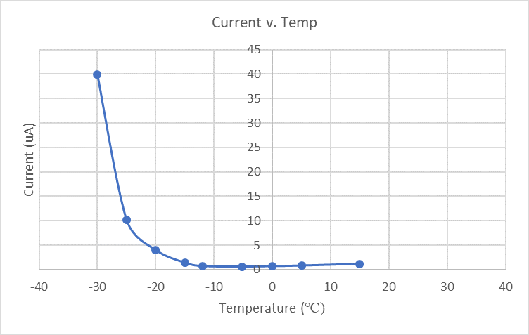
We are using an MSP430G2333 in our design. We have had issues with high sleep current at cold temperatures (minimum of -30 deg.C). Through further testing, we found that the source of all of this excess current at cold temperatures is the MSP430G2333 (DVCC pin). The following is a plot showing an example of this high sleep current that we see in our board. The current was measured at the power source in this test.


To determine which part of our design could be causing this high sleep current, we decided to run a series of tests. The first test was to narrow out the possibility of the problem being in the MSP430 device itself. We programmed an MSP430G2 LaunchPad (MSP430G2553) with example code from CCS (msp430g2xx3_lpm3_vlo.c), disconnected LED1, and ran a test measuring the overall current at cold temperatures, down to -30 deg.C. We found that this test also resulted in high sleep current. The following is a plot of the results of this test.


Why are we seeing this increase of sleep current as temperature decreases? 

  • Hello Madelyn,

    there are multiple possibilities, why you're seeing an increased current.

    With -30degC one e.g. needs to be very careful with moisture condensation, which in combination with soldering residuals could cause leakages.

    The same could be the root cause for a floating node, if a GPIO is not terminated properly.

    In the end, to be able to investigate this in more detail we need the full schematics, including code(which you pointed to in case of the code example).

    Another question would be, whether you have tested just one sample of the MSPG2333 and related HW, or multiple with same results. Just to make sure you're not running into some kind of ESD damage related device failure.

    If you want to share data privately with us, you can request a friendship with me, and then we can share data privately.

    Best regards

    Peter

  • Hi Peter,

    We have tested multiple samples of our design with the MSP430G2333 and seen the same issues with high sleep current throughout all of these tests.

    I have requested friendship with you so that I can share schematic files with you. Although, I am not sure if that will help answer the question about why we are also seeing this same high sleep current on the MSP430G2 LaunchPad, as shown in the second plot from my original post.

    Regards,

    Madelyn

  • Hi Madelyn,

    with the LP, I assume you have removed all the connections to the debug section, and are powering the MSP430 from an external power supply?

    Are you using the MSP-EXP430G2 or the MSP-EXP430G2ET? Just to make sure which exact HW you're using.

    Best regards

    Peter

  • Hi Madelyn,

    one question on the MSP430 configuration you're using. Are you applying any crystal or resonator to the MSP430 at P2.6/P2.7? In case not, are you switching these pins back to GPIO functionality? I am asking as the code example is not doing this. This is a clear mistake as the code example is using the VLO, and per default the P2.6/P2.7 are configured for oscillator functionality. Potentially this is the root cause for the higher current at lower temperatures.

    Best regards

    Peter

  • Hi Peter,

    In the testing Madelyn did on the LaunchPad, all of the programming jumpers to the FET were disconnected, and the board was powered via a bench supply from the external power connections. Also, we confirmed that this is just the MSP-EXP430G2 LaunchPad.

    Additionally, according to the G2xx User's Guide, "The LFXT1 crystal oscillators are disabled when the VLO is selected reducing current consumption." Your comment would imply that the User's Guide is incorrect as well as the code example, which would explain a lot of our confusion.

    Regardless, we will add in a clear of the P2SEL and P2SEL2 registers to ensure these pins are set as GPIO before terminating them, and try the test again.

    Is there any other reason you can think of that this could be an issue in the meantime?

  • Hi Tyler,

    as stated, the other topic is the potential condensation of moisture on the PCB. It is of course not easy to check within the climate chamber, whether you're running into that issue. But the current values look to me as a floating node behavior.

    I just found one fundamental mistake in the code example, and that probably applies also to your case. Independent of the package, which you're using, means no matter whether P3.x is available on physical GPIOs, they exist on the die of every version of this device portfolio. The code example though does not initialize Port 3.x, thus the entire Port3.x is floating.

    As per datasheet note "NOTE: The pull-down resistors of port P3 should be enabled by setting P3REN.x = 1." you need to terminate them by enabling the internal resistors in case you're using a package variant, where they are not available at physical pins.

    Best regards

    Peter

  • Peter,

    We do our best to control humidity in the temperature chamber we use by driving it hot first with the door open, then close it up and drive down to the cold temperatures.

    We will modify the code example for the LaunchPad to set port 3 to all input pull-downs as well for the next run of testing.

    I will say that on our PCBs we have initialized all of the pins as GPIOs, but we have a few unused pins we did not terminate in that same fashion. One we had as an input high and the other three were output low, none of which had the pull resistors enabled. I've modified that code to try and run a test for that board as well.

    We'll update this thread once we've completed the testing.

  • Hi Peter,

    We made changes to the code example for the LaunchPad, as shown in the pasted code below:

    #include <msp430.h>
    
    int main(void)
    {
    
        WDTCTL = WDTPW | WDTHOLD;      // Hold the dog
        BCSCTL1 |= DIVA_1;                           // ACLK/2
        BCSCTL3 |= LFXT1S_2;                      // ACLK = VLO
        P1DIR = 0xFF;                                     // All P1.x outputs
        P1OUT = 0;                                          // All P1.x reset
        P2SEL = 0; P2SEL2 = 0;                     //
        P2DIR = 0xFF;                                     // All P2.x outputs
        P2OUT = 0;                                          // All P2.x reset
        P3REN = 0x00;
        P3DIR = 0;
        P3OUT = 0;
    
        __bis_SR_register(LPM3_bits + GIE);     // Enter LPM3                             // All P2.x reset
    
    }

    We tested the LaunchPad with this code modification, down to -30 deg C. We saw the same results as the test prior: Current increased steadily up to about 70uA.

    Additionally, the code for our PCB was also modified, as Tyler mentioned. The unused GPIOs are now terminated as inputs and held low by the internal resistors. We ran a test after making these code changes, once again down to -30 deg C. In this test, we saw an improvement in the sleep current values, but the issue still remained. We saw a maximum sleep current value of about 20uA at -30 deg C as opposed to the previous results (before code modification) of about 40uA. However, we would hope for more of an improvement than that, of course.

    At this point, we wanted to confirm that moisture was not an issue in these tests. We repeated the test above, with our same PCB (still with the modified code). However, this time, we set the temperature chamber to sit at hot temperatures (60 deg C) for a while, so that it would dry out the chamber prior to running our cold-temperature test. We also added a bowl of silica gel desiccant to the temperature chamber to absorb possible excess moisture during the test.The results of this were the same as the previous test. The sleep current, again, reached about 20uA at -30 deg C. Based on this result, it seems that moisture is not a problem in our tests. 

  • Hi Madelyn,

    many thanks for the additional information, especially on the moisture tests.

    Unfortunately the code for the tests with the LaunchPad is definitely not corrected in the required way.

    At least what you pasted in here, would still be generating floating nodes at the entire P3.x port.

    P3REN = 0x00;   This means integrated resistors are off

    P3DIR = 0;      This means all P3.x are switched to input >> floating nodes
    P3OUT = 0;      With disabled resistors and in input mode, this does not have an effect.
    There are two options:
    1.
    P3DIR = 0xFF;          All P3.x to output. This would already be sufficient as no floating node can occur. Though as PxOUT is undefined on POR, the pins could drive low or high. Thus I would tend to set also
    P3OUT = 0x00;        This switches all P3.x to output low
    2.
    P3REN = 0xFF;        All integrated resistors at P3.x active
    P3DIR = 0x00;          default state after POR, thus not really necessary
    P3OUT = 0x00;        switch resistors to Pull-Down direction, although for the floating node avoidance the direction pull-up/-down does not make a difference.
    Please try this with the LP. This should give you the expected values. Once we have reached that, we can start looking into why your HW just went down to 20µA instead of to the expected values.
    Best regards
    Peter
  • Hi Peter, 

    Thanks for your corrections to the code. I implemented those changes and it seems to have corrected the cold temperature high sleep current issue that we were seeing in the LaunchPad. 

    To continue the investigation of the cold temperature high sleep current in our PCBs, I can privately send you our schematic.

  • Hi Madelyn,

    please do so. Please also include the information on how you're configuring all the MSP430 peripherals and GPIOs, as I need to check this against your schematics.

    Best regards

    Peter

  • To All,

    we have handled the case offline due to private customer specific information.

    The resolution of the case was basically the avoidance of floating nodes, where in case of the MSP430G2333 also the physically not accessible Port3 needs to be considered, as stated in the device datasheet.

    Best regards

    Peter

**Attention** This is a public forum