This thread has been locked.

If you have a related question, please click the "Ask a related question" button in the top right corner. The newly created question will be automatically linked to this question.

EVM430-FR6047: USB HID connection or UART connection troubleshoot

Part Number: EVM430-FR6047


Hello,

I wanted to read the DTOF values from the evm board by Raspberry Pi, through the USB HID UART connection or just UART connection. I have set the baud-rate to 115,200, and I don't receive any values.

I have also flashed the suggested code for enabling UART onto the evm430 launchpad board. But I am not getting anything. And could you confirm me the position of jumpers for this operation.  Please advice as soon as possible as I'm in a bit of a crunch situation.  It would be helpful if you could give a step by step guide on how to achieve this.

Thank You.

  • Hello Eddie,

    Thank you for replying.

    I did follow that post and made the necessary changes to the demo program and flashed it. But Im not able to receive anything through the USB HID.

    Thanks and Regards,

    Ashish 

  • Ashish,

    This would not go through the USB HID.  It should use the MSP Application UART.  See the screen shot below from device manager.  Are you using this COM port?


  • I dont know if it helps, but when I was executing the code line by line on CCS, the program used to get stuck in the line shown below,; this file is in 

    ussSwLibCommon.c

  • I have a linux machine and I am also running linux on Raspberry Pi, I tried by connecting UART pins to it and still did not get the information from the EVM430.

    Thank You,

    Ashish

  • Just to be sure, the UART wires are taken out from J2 Tx pin. I wanted to rule this doubt out as well.

    I also tried with a Beaglebone, but unfortunately, it was the same there too.

  • Yes, this should be on J2 TX pin.  Be sure that you are connecting your wire to the side of the header closest to the TXD silkscreen. 

    To check if the code is running properly, you may also want to place the jumper on J2 TX and use the USB interface with a Windows PC and terminal application.  Just as a quick sanity check. 

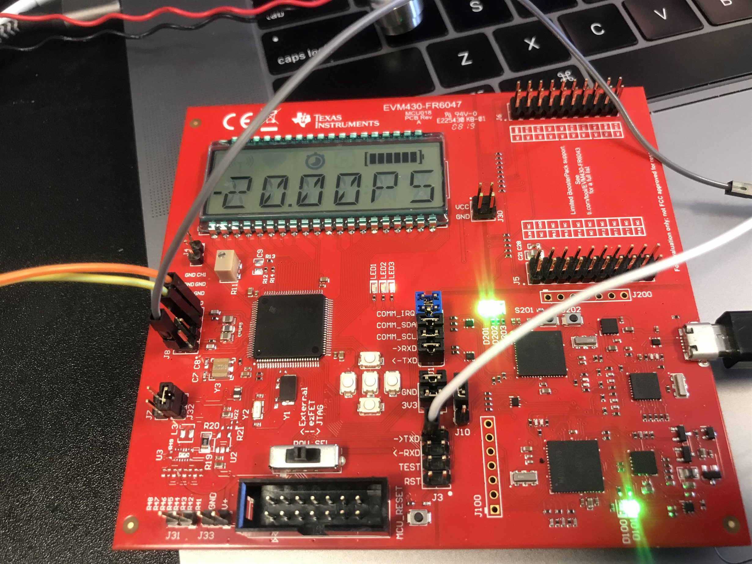
  • Yes, I have attached the pins as said, could you verify the jumpers and the connections? I wanted to read the data on the linux terminal.

    The white wire is the UART Tx wire. 

    The gray wire is connected to the ground of beaglebone.

    Orange and yellow wires are connected to the positive and the negative of the Steminc ultrasonic sensors.  


  • Jumper configuration looks good.  TXD connection is correct.  I'm not sure that it would make a difference, but you may want to try using a ground point from the MCU ground instead of USS ground.  There is GND available on J33 or J30 that could be used.

    Were you able to test placing the TXD jumper on J3 and using USB to transmit to a PC?  Another test could be to connect the TXD pin to a oscilloscope or logic analyzer to verify the UART signal is there. 

  • The TXD pin to oscilloscope is generating a proper square signal. So, is the UART on the EVM working fine?

    And the silkscreen on the EVM just shows -20.00PS for the DTOF values, when the 1 MHZ STEMINC ultrasonic sensors  are connected to it ( not to a pipe).  is that right?

  • Ashish,

    Yes, that sounds like the UART is working.  Connecting to a PC via USB could confirm that the data looks correct, but it sounds like it is at least transmitting data if you see the signal on oscilloscope. 

    If it is staying fixed at -20ps, this is not correct.  The DToF should be moving around some with each measurement.  What is your setup?  Are you trying to measure flow rate or something else?  1MHz transducers would need to be in water to receive a proper signal as the attenuation in air would be too high.  Are you able to receive a proper ADC signal using the Design Center GUI?  The first step should be making sure you can obtain a good ADC signal.  The FAQ below has some good pointers on getting this started.

    http://www.ti.com/lit/an/slaa837a/slaa837a.pdf    

  • Thank you !!!  I did get the output... but it just had the following symbols. I checked the baud-rate (115200) and everything.

    2��2��2��2��2�

    How do I correct this?

    The GUI did not receive any signal ... the ADC is empty, I did keep getting SAPH error and The GUI is getting a Algorithm error ; code :126 ; error message: No signal detected in up and downstream channel errors. How do I resolve this ?

  • The GUI is getting a Algorithm error ; code :126 ; error message: No signal detected in up and downstream channel 

  • This is indicating that the receiving transducers are not seeing a signal.  First, check your physical set up.  Make sure the transducers are in water and oriented so that they will be able to receive the signal from the transmitting transducer.  In a pipe, this is typically done by having the transducers directly facing each, with reflectors at 45 degree angles, or in a "V" configuration where the signal is reflected off the pipe.  Section 1 of the document below shows some example diagrams. 

    http://www.ti.com/lit/an/slaa889/slaa889.pdf

    Once you have your transducers in water and configured so that they can receive a signal, you may need to adjust the gap between pulse start and ADC capture in the GUI.  To find what the gap needs to be, you can extend the capture duration from the advanced parameters tab to the maximum value and then take an ADC capture and adjust the gap until you are able to see the signal.  Once the signal is captured, you can start to reduce the duration to capture just the window you need.   

    If you can provide some more information about your use case, I can make some other suggestions.  The software we provide is intended to work with 2 transducers in water where one transmits and the other receives and then the TX and RX are reversed.  This is known as upstream and downstream.  The document above explains this method in more detail.

  • Thank you Eddie, 

    I got the UART working. 

    I am using it to measure the flow of water through the pipe (as of now I cannot have the transducers in contact with the water). So, I put the the 1 MHz transducers in a glass of water ... but I did not receive anything there either. The GUI still displays the same error. The TDOF value is just constant at 20.000. I checked with the oscilloscope The board is transmitting but not receiving anything.

     Are my methods correct ?

  • Glad to hear the UART is working now.

    Just want to confirm that you have both transducers connected to the EVM.  I noticed in your earlier picture, only 1 transducer appeared to be connected.  Figure 14 in the document below shows a pair of transducers connected to the EVM.  Be sure they are connected to CH0 and CH1.  The silkscreen to the right of the J8 header shows the signals for each pin.  If this is correct, point the transducers towards each other and provide around 7-8cm spacing.  Once you have this in place, you can start to adjust the gap as described earlier until you are able to find the signal.  Depending on what signal level you receive, you may also need to adjust the gain in the GUI.  Ideally, you want to have around +/-900 ADC counts in the ADC capture. 

    http://www.ti.com/lit/ug/tidudn0/tidudn0.pdf  

    Audiowell also makes some brass pipes with transducers installed that are good for testing.  The default configuration of the GUI works well with the DN-25 pipe.

    https://www.audiowellsensor.com/ultrasonic-flow-sensor-module/ultrasonic-flow-sensor-with-brass-pipe/

  • Hello Eddie,

    Sorry for the delay, But the UART is just transmitting 2 and some symbols which cannot be read. The baud rate is set to 115,200 bps. I can see the data on the oscilloscope as well.  Do you think there is some other issue?

  • Ashish,

    Typically, this indicates an issue with the baud rate on the receiving side.  Have you been able to test with it connected to a PC terminal?  You could do this by placing the TX and RX jumpers and connecting to the board on a PC terminal with the correct baud rate set.  The port should show as Application UART in device manager.

**Attention** This is a public forum