Part Number: CC430F6137
Dear TI team,
We are developing a product based on TI CC430F6137. Below is a snapshot of the device initialization routine which enables XT1 CLK that source from a 32.768KHZ watch crystal. In addition, the XT1_CLK is used as a reference signal to PLL/DCO and generate MCLK.
During the course of stepping through the initialization routine, we occasionally encountered a situation where MCU is trapped in a do-while loop (BOLD font) , because DCOFFG flag always set to 1, regardless of the fact that it is cleared in the loop. This situation happens once in a while when we rapidly switch on/off power to CC430F6137 for multiple times in a role. As soon as the device enters this state, resetting the device through system reset pin doesn't help as the MCU keeps on being trapped in the do-while loop. The only way to resolve the issue is to recycle the power to the MCU in a normal manner. Would you please review our initialization code and give us advice for any improvement that can be implemented to resolve the issue we experienced? Thank you.
Best regards,
Peter
MCU Clock Initialization routine
{
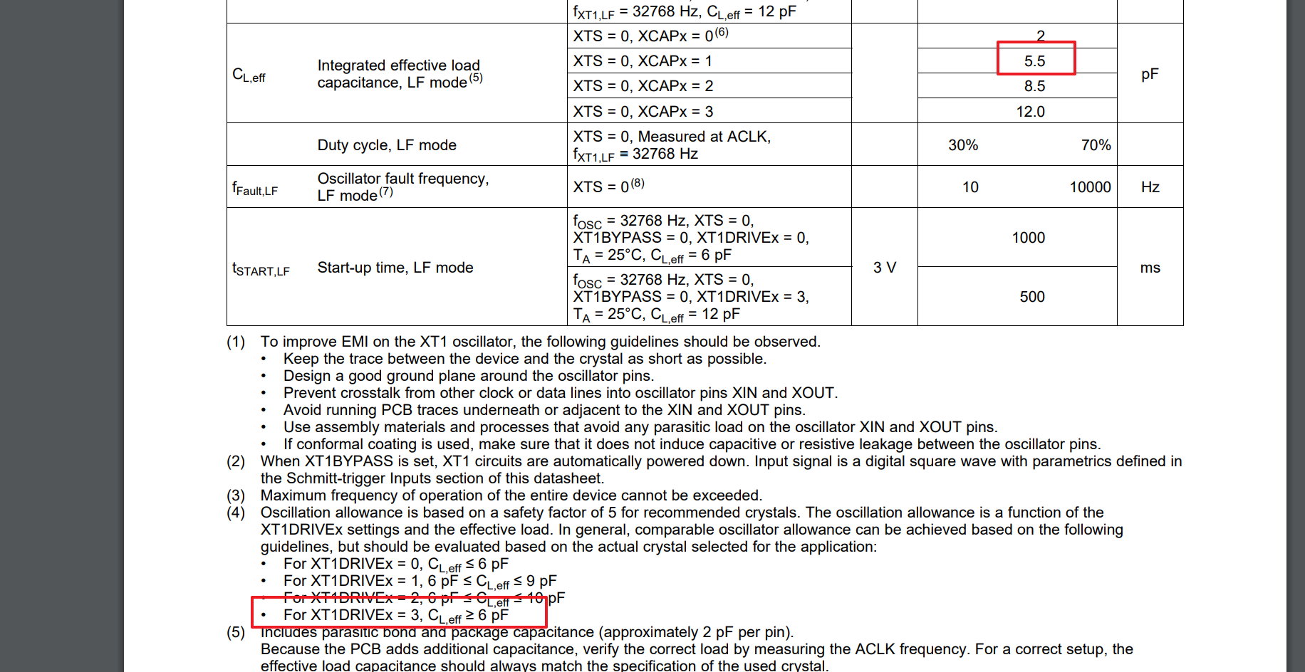
UCSCTL6 &= ~XCAP_3; //Clear XCAP value
UCSCTL6 |= XCAP_1; //Set XCAP value to 6pf
P5SEL |= (BIT0 | BIT1); /* set P5.0 & P5.1 for external source of XT1 */
__delay_cycles(375000);
UCSCTL3 &= ~SELREF_7; /* Set DCO FLL reference = XT1 */
UCSCTL4 |= SELA_2; /* Set ACLK = REFO */
__bis_SR_register(SCG0); /* Disable the FLL control loop */
UCSCTL0 = 0x0000; /* Set lowest possible DCOx, MODx */
UCSCTL1 = DCORSEL_5; /* Select DCO range 24MHz operation */
UCSCTL2 = FLLD_1 + 499; /* (499 + 1) * 32768 = 16384000Hz */
__bic_SR_register(SCG0); /* Enable the FLL control loop */
/* Worst-case settling time for the DCO when the DCO range bits have been
* changed is n x 32 x 32 x f_MCLK / f_FLL_reference.
* 32 x 32 x 16 MHz / 32,768 Hz = 500000 = MCLK cycles for DCO to settle
*/
__delay_cycles(500000); /* delay cycle is updated according to formula */
/* Loop until XT1,XT2 & DCO fault flag is cleared */
do
{
UCSCTL7 &= ~(XT2OFFG + XT1LFOFFG + DCOFFG) /* Clear XT2,XT1,DCO fault flags */
SFRIFG1 &= ~OFIFG; /* Clear fault flags */
}while (SFRIFG1&OFIFG); /* Test oscillator fault flag */
}