This thread has been locked.

If you have a related question, please click the "Ask a related question" button in the top right corner. The newly created question will be automatically linked to this question.

MSP430FR5994: RST pullup/pulldown clarification

Part Number: MSP430FR5994
Other Parts Discussed in Thread: MSP-EXP430FR5994, MSP-FET,

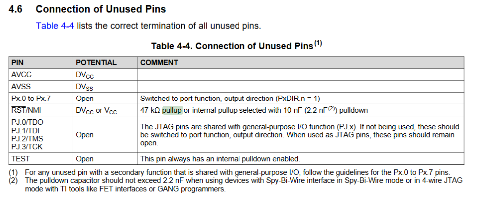
I am reviewing the RST pin configuration and I'm a little confused about the external pullup and pulldown requirements for the RST line.  We are using the default configuration for the RST pin configuration, which enables the internal pullup resistor.  According to the MSP430FR Family User's Guide, it states that the RST line shall have a "47-kΩ pullup or internal pullup selected with 2.2-nF (10-nF(2)) pulldown" with more notes stating that not to use more than a 2.2nF pulldown cap if you want to use SPW or 4-wire JTAG.  So from my understanding you should either have a 47-kΩ pullup resistor or a 2.2-nF or less pulldown capacitor on the RST pin but not both.  However, the MSP-EXP430FR5994 demo board has both a 47-kΩ pullup resistor and a 1-nF pulldown capacitor attached to the RST pin.

Could you clarify what is actually required for pullup/pulldown on the RST pin when it is configured as a reset input with the internal pullup resistor?  We are using the SPW interface from the MSP-FET on the MSP-EXP430FR5994 for our debugger if that matters.  Could you also clarify the purpose of the pulldown capacitor?  I've never seen that on a reset line before.

Thanks,

Bryan

  • Hi Bryan,

    Yes, you definitely need both.  The external 47kohm resistor and capacitor (2.2nF is the max, but 1.0nf is more typical) are needed to prevent noise spikes from entering the RST pin and causing spurious resets.

    This is true for either 4-wire JTAG or 2-wire SPY-BY-WIRE.

    Note, using a capacitor > 2.2nF really doesn't buy you much and can affect the programmer's ability to connect and place the MCU into programming mode.

  • Dennis,

    Thanks for the quick reply.  If both are required, then what is the purpose of the internal pullup resistor on the RST pin?  I'm asking because we did not include the external pullup resistor because we did not think it was necessary based upon the documentation.

    Bryan

  • Bryan,

    For many applications using the internal pull up resistor is fine.  For some applications where there is a potential of large amounts of noise, the internal pull up resistor and no external capacitor may leave the RST vulnerable to false resets. The R and C combination are recommended but if you didn't design these in you now know what they are used for and should you encounter issues with the RST pin you know what to do.

    Also, from the MSP430FR5994 datasheet:

    Here is another E2E thread asking same question, FYI.

**Attention** This is a public forum